(a)
The phasor diagram if the capacitance is
(a)
Answer to Problem 66PQ
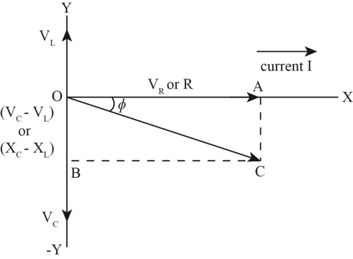
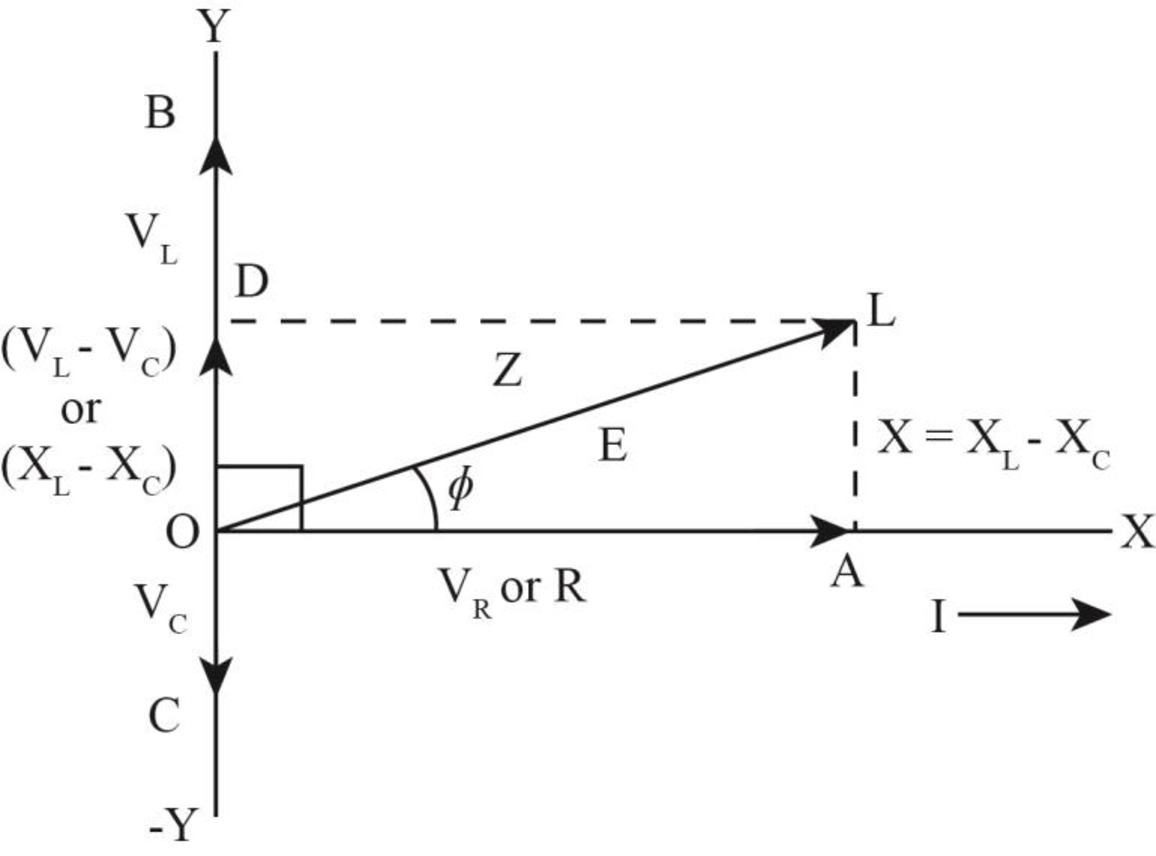
The phasor diagram of the circuit is shown below.
Explanation of Solution
Write the expression for the impedance.
Here,
Write the expression to calculate the inductive reactance.
Here,
Write the expression for the capacitive reactance.
Here,
Substitute the
Write the expression for maximum current in the circuit.
Here,
Write the expression for phase angle.
Conclusion:
Substitute
Substitute
Substitute
The phase angle is
The inductive reactance is less than the capacitive reactance. Hence, the phasor angle is negative.
The phasor diagram of the circuit is shown below. 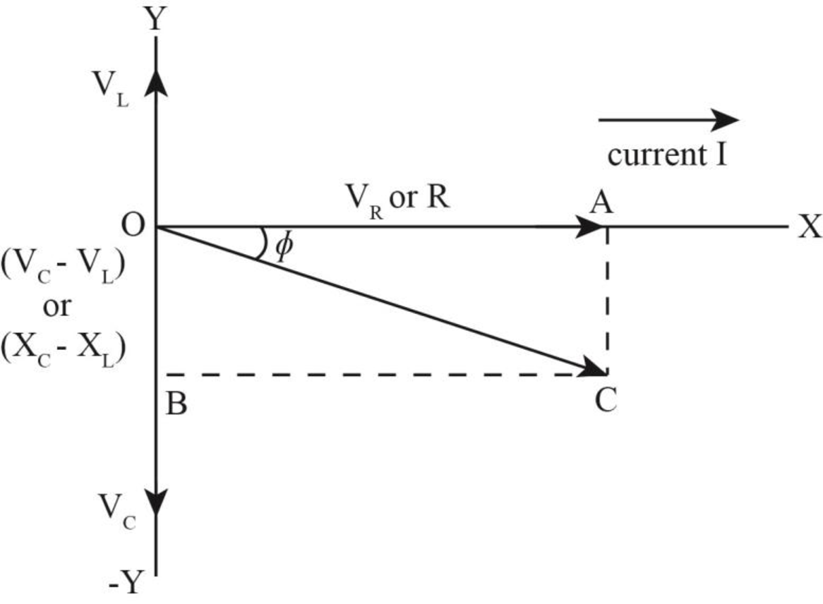
Figure (1)
(b)
The phasor diagram if the capacitance is
(b)
Answer to Problem 66PQ
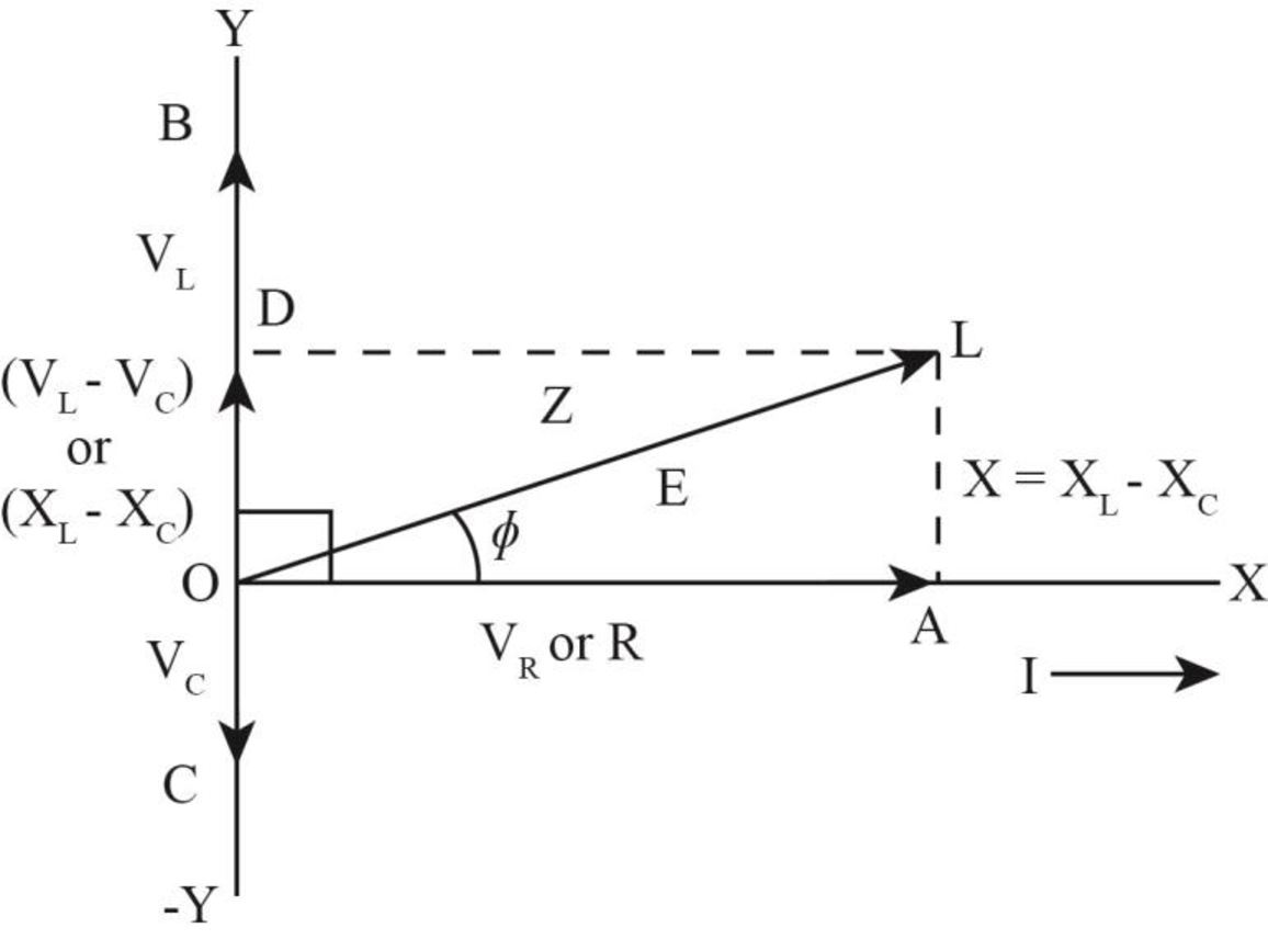
The phasor diagram of the circuit is shown below.
Explanation of Solution
Write the expression for the impedance.
Here,
Write the expression to calculate the inductive reactance.
Here,
Write the expression for the capacitive reactance.
Here,
Substitute the
Write the expression for maximum current in the circuit.
Here,
Write the expression for phase angle.
Conclusion:
Substitute
Substitute
Substitute
The phase angle is
The inductive reactance is less than the capacitive reactance. Hence, the phasor angle is negative.
The phasor diagram of the circuit is shown below.
Want to see more full solutions like this?
Chapter 33 Solutions
Physics for Scientists and Engineers: Foundations and Connections
- In the figure below, a semicircular conductor of radius R = 0.260 m is rotated about the axis AC at a constant rate of 130 rev/min. A uniform magnetic field of magnitude 1.22 T fills the entire region below the axis and is directed out of the page. R Pout (a) Calculate the maximum value of the emf induced between the ends of the conductor. 1.77 v (b) What is the value of the average induced emf for each complete rotation? 0 v (c) How would your answers to parts (a) and (b) change if the magnetic field were allowed to extend a distance R above the axis of rotation? (Select all that apply.) The value in part (a) would increase. The value in part (a) would remain the same. The value in part (a) would decrease. The value in part (b) would increase. The value in part (b) would remain the same. The value in part (b) would decrease. × (d) Sketch the emf versus time when the field is as drawn in the figure. Choose File No file chosen This answer has not been graded yet. (e) Sketch the emf…arrow_forwardPortfolio Problem 2. A particle of mass m slides in a straight line (say along i) on a surface, with initial position x ©0 and initial velocity Vo > 0 at t = 0. The = particle is subject to a constant force F = -mai, with a > 0. While sliding on the surface, the particle is also subject to a friction force v Ff = -m fo = −m fov, with fo > 0, i.e., the friction force has constant magnitude mfo and is always opposed to the motion. We also assume fo 0, and solve it to find v(t) and x(t). How long does it take for the particle to come to a stop? How far does it travel? (b) After coming to a stop, the particle starts sliding backwards with negative velocity. Write the equation of motion in this case, and solve it to find the time at which the particle returns to the original position, x = 0. Show that the final speed at x 0 is smaller than Vo. = Express all your answers in terms of a, fo and Vo.arrow_forward= Portfolio Problem 1. A particle of mass m is dropped (i.e., falls down with zero initial velocity) at time t 0 from height h. If the particle is subject to gravitational acceleration only, i.e., a = −gk, determine its speed as it hits the ground by solving explicitly the expressions for its velocity and position. Next, verify your result using dimensional analysis, assuming that the general relation is of the form v = khag³m, where k is a dimensionless constant.arrow_forward
- Review Conceptual Example 2 before attempting this problem. Two slits are 0.158 mm apart. A mixture of red light (wavelength = 693 nm) and yellow-green light (wavelength = 567 nm) falls on the slits. A flat observation screen is located 2.42 m away. What is the distance on the screen between the third-order red fringe and the third-order yellow- green fringe? m = 3 m = 3 m= 0 m = 3 m = 3 Fringes on observation screenarrow_forwardIn the figure below, a semicircular conductor of radius R = 0.260 m is rotated about the axis AC at a constant rate of 130 rev/min. A uniform magnetic field of magnitude 1.22 T fills the entire region below the axis and is directed out of the page. In this illustration, a wire extends straight to the right from point A, then curves up and around in a semicircle of radius R. On the right side of the semicircle, the wire continues straight to the right to point C. The wire lies in the plane of the page, in a region of no magnetic field. Directly below the axis A C is a region of uniform magnetic field pointing out of the page, vector Bout. If viewed from the right, the wire can rotate counterclockwise, so that the semicircular part can rotate into the region of magnetic field. (a) Calculate the maximum value of the emf induced between the ends of the conductor. V(b) What is the value of the average induced emf for each complete rotation? Consider carefully whether the correct answer is…arrow_forwardA coil of 15 turns and radius 10.0 cm surrounds a long solenoid of radius 2.20 cm and 1.00 103 turns/meter (see figure below). The current in the solenoid changes as I = 6.00 sin(120t), where I is in amperes and t is in seconds. Find the induced emf (in volts) in the 15-turn coil as a function of time. (Do not include units in your answer.) =arrow_forward
- A coil of 15 turns and radius 10.0 cm surrounds a long solenoid of radius 1.80 cm and 1.00 103 turns/meter (see figure below). The current in the solenoid changes as I = 5.00 sin(120t), where I is in amperes and t is in seconds. Find the induced emf (in volts) in the 15-turn coil as a function of time. (Do not include units in your answer.) =arrow_forwardWhich vowel does this graph represent (”ah,” “ee,” or “oo”)? How can you tell? Also, how would you be able to tell for the other vowels?arrow_forwardConcept Simulation 26.4 provides the option of exploring the ray diagram that applies to this problem. The distance between an object and its image formed by a diverging lens is 5.90 cm. The focal length of the lens is -2.60 cm. Find (a) the image distance and (b) the object distance.arrow_forward
- A bat is flying toward a cave wall at 27.0 m/s. What is the frequency of the reflected sound that it hears, assuming it emits sound at 52.0 kHz? The speed of sound is 341.5 m/s. Multiple Choice о 60.9 kHz О 56.5 kHz о 61.3 kHz О 56.1 kHzarrow_forwardCompare the slope of your Data Table 2 graph to the average wavelength (Ave, l) from Data Table 2 by calculating the % Difference. Is the % Difference calculated for the wavelength in Data Table 2 within an acceptable % error? Explain why or why not?arrow_forwardThe slope of a graph of velocity, v, vs frequency, f, is equal to wavelength, l. Compare the slope of your Data Table 1 graph to the average wavelength (Ave, l) from Data Table 1 by calculating the % Difference.arrow_forward
 Physics for Scientists and Engineers: Foundations...PhysicsISBN:9781133939146Author:Katz, Debora M.Publisher:Cengage Learning
 College PhysicsPhysicsISBN:9781285737027Author:Raymond A. Serway, Chris VuillePublisher:Cengage Learning
 College PhysicsPhysicsISBN:9781305952300Author:Raymond A. Serway, Chris VuillePublisher:Cengage Learning
 Physics for Scientists and Engineers with Modern ...PhysicsISBN:9781337553292Author:Raymond A. Serway, John W. JewettPublisher:Cengage Learning
 Physics for Scientists and EngineersPhysicsISBN:9781337553278Author:Raymond A. Serway, John W. JewettPublisher:Cengage Learning


