
VECTOR MECHANIC
12th Edition
ISBN: 9781264095032
Author: BEER
Publisher: MCGRAW-HILL HIGHER EDUCATION
expand_more
expand_more
format_list_bulleted
Concept explainers
Videos
Textbook Question
Chapter 3.3, Problem 3.81P
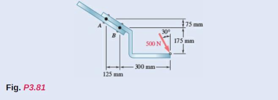
A 500-N force is applied to a bent plate as shown. Determine (a) an equivalent force-couple system at B, (b) an equivalent system formed by a vertical force at A and a force at B.
Expert Solution & Answer
Want to see the full answer?
Check out a sample textbook solution
Students have asked these similar questions
(read image)
Problem 3.30
A piston-cylinder device contains 0.85 kg of refrigerant- 134a at -10°C. The piston that is free to move has a mass of 12 kg and a diameter of 25 cm. The local atmospheric pressure is 100 kPa. Now, heat is transferred to refrigerant-134a until the temperature is 15°C. Determine (a) the final pressure, (b) the change in the volume of the refrigerant, and (c) the change in the enthalpy of the refrigerant-134a.
please show Al work step by step
Part 1
The storage tank contains lubricating oil of specific gravity 0.86 In one inclined side of the tank,
there is a 0.48 m diameter circular inspection door, mounted on a horizontal shaft along the centre
line of the gate. The oil level in the tank rests 8.8 m above the mounted shaft. (Please refer table
01 for relevant SG, D and h values).
Describe the hydrostatic force and centre of pressure with the aid of a free body diagram of the
inspection door.
Calculate the magnitude of the hydrostatic force and locate the centre
of pressure.
45°
Estimate the moment that would have to be applied to the shaft to
open the gate.
Stop
B
If the oil level raised by 2 m from the current level, calculate the new
moment required to open the gate.
Figure 01
Chapter 3 Solutions
VECTOR MECHANIC
Ch. 3.1 - A foot valve for a pneumatic system is hinged at...Ch. 3.1 - 3.2A foot valve for a pneumatic system is hinged...Ch. 3.1 - It is known that a vertical force of 200 lb is...Ch. 3.1 - A 300-N force is applied at A as shown. Determine...Ch. 3.1 - A 300-N force is applied at A as shown. Determine...Ch. 3.1 - An 8-lb force P is applied to a shift lever....Ch. 3.1 - For the shift lever shown, determine the magnitude...Ch. 3.1 - An 11-lb force P is applied to a shift lever. The...Ch. 3.1 - Rod AB is held in place by the cord AC. Knowing...Ch. 3.1 - Rod AB is held in place by the cord AC. Knowing...
Ch. 3.1 - 3.11 and 3.12The tailgate of a car is supported by...Ch. 3.1 - 3.11 and 3.12The tailgate of a car is supported by...Ch. 3.1 - 3.13 and 3.14It is known that the connecting rod...Ch. 3.1 - 3.13 and 3.14It is known that the connecting rod...Ch. 3.1 - Form the vector product P1 P2 and use the result...Ch. 3.1 - The vectors P and Q are two adjacent sides of a...Ch. 3.1 - A plane contains the vectors A and B. Determine...Ch. 3.1 - A line passes through the points (4 m, 3 m) and (2...Ch. 3.1 - Prob. 3.19PCh. 3.1 - Determine the moment about the origin O of the...Ch. 3.1 - Before the trunk of a large tree is felled, cables...Ch. 3.1 - The 12-ft boom AB has a fixed end A. A steel cable...Ch. 3.1 - A 200-N force is applied as shown to the bracket...Ch. 3.1 - A force P of magnitude 200 N acts along the...Ch. 3.1 - A 6-ft-long fishing rod AB is securely anchored in...Ch. 3.1 - A precast concrete wall section is temporarily...Ch. 3.1 - In Prob. 3.22, determine the perpendicular...Ch. 3.1 - In Prob. 3.23, determine the perpendicular...Ch. 3.1 - In Prob. 3.24, determine the perpendicular...Ch. 3.1 - In Prob. 3.25, determine the perpendicular...Ch. 3.1 - In Prob. 3.25, determine the perpendicular...Ch. 3.1 - In Prob. 3.26, determine the perpendicular...Ch. 3.1 - In Prob. 3.26, determine the perpendicular...Ch. 3.1 - Determine the value of a that minimizes the...Ch. 3.2 - Given the vectors P = 2i + j + 2k, Q = 3i + 4j ...Ch. 3.2 - Form the scalar product B C and use the result...Ch. 3.2 - Three cables are attached to the top of the tower...Ch. 3.2 - Three cables are attached to the top of the tower...Ch. 3.2 - Knowing that the tension in cable AC is 280 lb,...Ch. 3.2 - Prob. 3.40PCh. 3.2 - Ropes AB and BC are two of the ropes used to...Ch. 3.2 - Prob. 3.42PCh. 3.2 - The 20-in. tube AB can slide along a horizontal...Ch. 3.2 - Solve Prob. 3.43 for the position corresponding to...Ch. 3.2 - Determine the volume of the parallelepiped of Fig....Ch. 3.2 - Given the vectors P = 3i + 2j + k, Q = 5i + j 2k,...Ch. 3.2 - A crane is oriented so that the end of the 25-m...Ch. 3.2 - 3.48The 25-m crane boom AO lies in the yz plane....Ch. 3.2 - To loosen a frozen valve, a force F with a...Ch. 3.2 - 3.50When a force F is applied to the handle of the...Ch. 3.2 - The 0.61 1.00-m lid ABCD of a storage bin is...Ch. 3.2 - 3.52The 0.61 1.00-m lid ABCD of a storage bin is...Ch. 3.2 - A farmer uses cables and winch pullers B and E to...Ch. 3.2 - Solve Prob. 3.53 when the tension in cable AB is...Ch. 3.2 - A force P of magnitude 520 lb acts on the frame...Ch. 3.2 - 3.56A force P acts on the frame shown at point E....Ch. 3.2 - The frame ACD is hinged at A and D and is...Ch. 3.2 - In Prob. 3.57, determine the moment about the...Ch. 3.2 - The triangular plate ABC is supported by...Ch. 3.2 - 3.60The triangular plate ABC is supported by...Ch. 3.2 - A regular tetrahedron has six edges of length a. A...Ch. 3.2 - Prob. 3.62PCh. 3.2 - Prob. 3.63PCh. 3.2 - In Prob. 3.55, determine the perpendicular...Ch. 3.2 - In Prob. 3.56, determine the perpendicular...Ch. 3.2 - In Prob. 3.57, determine the perpendicular...Ch. 3.2 - In Prob. 3.58, determine the perpendicular...Ch. 3.2 - In Prob. 3.59, determine the perpendicular...Ch. 3.2 - In Prob. 3.60, determine the perpendicular...Ch. 3.3 - Two 80-N forces are applied as shown to the...Ch. 3.3 - Two parallel 60-N forces are applied as shown to...Ch. 3.3 - A multiple-drilling machine is used to drill...Ch. 3.3 - Four pegs of the same diameter are attached to a...Ch. 3.3 - Prob. 3.74PCh. 3.3 - The shafts of an angle drive are acted upon by the...Ch. 3.3 - If P = 0 in the figure, replace the two remaining...Ch. 3.3 - 3.77If P = 20 lb in the figure, replace the three...Ch. 3.3 - The two couples shown are to be replaced with a...Ch. 3.3 - Solve part a of Prob. 3.78, assuming that two 15-N...Ch. 3.3 - Shafts A and B connect the gear box to the wheel...Ch. 3.3 - A 500-N force is applied to a bent plate as shown....Ch. 3.3 - Prob. 3.82PCh. 3.3 - Prob. 3.83PCh. 3.3 - A 30-lb vertical force P is applied at A to the...Ch. 3.3 - A worker tries to move a rock by applying a 360-N...Ch. 3.3 - A worker tries to move a rock by applying a 360-N...Ch. 3.3 - The shearing forces exerted on the cross section...Ch. 3.3 - Knowing that = 60, replace the force and couple...Ch. 3.3 - Three control rods attached to a lever ABC exert...Ch. 3.3 - A rectangular plate is acted upon by the force and...Ch. 3.3 - While tapping a hole, a machinist applies the...Ch. 3.3 - Prob. 3.92PCh. 3.3 - Replace the 250-kN force P with an equivalent...Ch. 3.3 - A 2.6-kip force is applied at point D of the...Ch. 3.3 - Prob. 3.95PCh. 3.3 - To keep a door closed, a wooden stick is wedged...Ch. 3.3 - A 46-lb force F and a 2120-lbin. couple M are...Ch. 3.3 - Prob. 3.98PCh. 3.3 - Prob. 3.99PCh. 3.3 - Prob. 3.100PCh. 3.4 - 3.101A 4-m-long beam is subjected to a variety of...Ch. 3.4 - A 4-m-long beam is loaded as shown. Determine the...Ch. 3.4 - Determine the single equivalent force and the...Ch. 3.4 - Five separate force-couple systems act at the...Ch. 3.4 - The weights of two children sitting at ends A and...Ch. 3.4 - Three stage lights are mounted on a pipe as shown....Ch. 3.4 - A beam supports three loads of given magnitude and...Ch. 3.4 - A 6 12-in. plate is subjected to four loads as...Ch. 3.4 - Gear C is rigidly attached to arm AB. If the...Ch. 3.4 - To test the strength of a 625 500-mm suitcase,...Ch. 3.4 - Prob. 3.111PCh. 3.4 - Prob. 3.112PCh. 3.4 - The roof of a building frame is subjected to the...Ch. 3.4 - Prob. 3.114PCh. 3.4 - A couple M and the three forces shown are applied...Ch. 3.4 - A machine component is subjected to the forces and...Ch. 3.4 - Prob. 3.117PCh. 3.4 - As follower AB rolls along the surface of member...Ch. 3.4 - A machine component is subjected to the forces...Ch. 3.4 - Two 150-mm-diameter pulleys are mounted on line...Ch. 3.4 - As an adjustable brace BC is used to bring a wall...Ch. 3.4 - In order to unscrew the tapped faucet A, a plumber...Ch. 3.4 - Prob. 3.123PCh. 3.4 - Four forces are applied to the machine component...Ch. 3.4 - A blade held in a brace is used to tighten a screw...Ch. 3.4 - A mechanic uses a crowfoot wrench to loosen a bolt...Ch. 3.4 - Four horizontal forces act on a vertical...Ch. 3.4 - Determine the magnitude of the force P for which...Ch. 3.4 - Prob. 3.129PCh. 3.4 - Prob. 3.130PCh. 3.4 - A concrete foundation mat of 5-m radius supports...Ch. 3.4 - Prob. 3.132PCh. 3.4 - Three forces of the same magnitude P act on a cube...Ch. 3.4 - A piece of sheet metal is bent into the shape...Ch. 3.4 - Prob. 3.135PCh. 3.4 - Prob. 3.136PCh. 3.4 - Two bolts at A and B are tightened by applying the...Ch. 3.4 - Two bolts at A and B are tightened by applying the...Ch. 3.4 - Prob. 3.139PCh. 3.4 - Prob. 3.140PCh. 3.4 - Prob. 3.141PCh. 3.4 - Prob. 3.142PCh. 3.4 - Replace the wrench shown with an equivalent system...Ch. 3.4 - Prob. 3.144PCh. 3.4 - Show that a wrench can be replaced with two...Ch. 3.4 - Show that a wrench can be replaced with two...Ch. 3 - A 300-N force P is applied at point A of the bell...Ch. 3 - A winch puller AB is used to straighten a fence...Ch. 3 - A small boat hangs from two davits, one of which...Ch. 3 - Prob. 3.150RPCh. 3 - A single force P acts at C in a direction...Ch. 3 - The 23-in. vertical rod CD is welded to the...Ch. 3 - In a manufacturing operation, three holes are...Ch. 3 - A 260-lb force is applied at A to the rolled-steel...Ch. 3 - The force and couple shown are to be replaced by...Ch. 3 - Prob. 3.156RPCh. 3 - Prob. 3.157RPCh. 3 - While using a pencil sharpener, a student applies...
Knowledge Booster


Learn more about
Need a deep-dive on the concept behind this application? Look no further. Learn more about this topic, mechanical-engineering and related others by exploring similar questions and additional content below.Similar questions
- From thermodynamics please fill in the table show all work step by steparrow_forwardThe 150-lb skater passes point A with a speed of 6 ft/s. (Figure 1) Determine his speed when he reaches point B. Neglect friction. Determine the normal force exerted on him by the track at this point. 25 ft B = 4x A 20 ft xarrow_forwardA virtual experiment is designed to determine the effect of friction on the timing and speed of packages being delivered to a conveyor belt and the normal force applied to the tube. A package is held and then let go at the edge of a circular shaped tube of radius R = 5m. The particle at the bottom will transfer to the conveyor belt, as shown below. Run the simulations for μ = 0, 0.1, 0.2, 0.3, 0.4, 0.5, 0.6 and determine the time and speed at which the package is delivered to the conveyor belt. In addition, determine the maximum normal force and its location along the path as measured by angle 0. Submit in hardcopy form: (0) Free Body Diagram, equations underneath, derivations (a) Your MATLAB mfile (b) A table listing the values in 5 columns: μ, T (time of transfer), V (speed of transfer), 0 (angle of max N), Nmax (max N) (c) Based on your results, explain in one sentence what you think will happen to the package if the friction is increased even further, e.g. μ = 0.8. NOTE: The ODE is…arrow_forward
- Patm = 1 bar Piston m = 50 kg 5 g of Air T₁ = 600 K P₁ = 3 bar Stops A 9.75 x 10⁻³ m² FIGURE P3.88arrow_forwardAssume a Space Launch System (Figure 1(a)) that is approximated as a cantilever undamped single degree of freedom (SDOF) system with a mass at its free end (Figure 1(b)). The cantilever is assumed to be massless. Assume a wind load that is approximated with a concentrated harmonic forcing function p(t) = posin(ωt) acting on the mass. The known properties of the SDOF and the applied forcing function are given below. • Mass of SDOF: m =120 kip/g • Acceleration of gravity: g = 386 in/sec2 • Bending sectional stiffness of SDOF: EI = 1015 lbf×in2 • Height of SDOF: h = 2000 inches • Amplitude of forcing function: po = 6 kip • Forcing frequency: f = 8 Harrow_forwardAssume a Space Launch System (Figure 1(a)) that is approximated as a cantilever undamped single degree of freedom (SDOF) system with a mass at its free end (Figure 1(b)). The cantilever is assumed to be massless. Assume a wind load that is approximated with a concentrated harmonic forcing function p(t) = posin(ωt) acting on the mass. The known properties of the SDOF and the applied forcing function are given below. • Mass of SDOF: m =120 kip/g • Acceleration of gravity: g = 386 in/sec2 • Bending sectional stiffness of SDOF: EI = 1015 lbf×in2 • Height of SDOF: h = 2000 inches • Amplitude of forcing function: po = 6 kip • Forcing frequency: f = 8 Hz Figure 1: Single-degree-of-freedom system in Problem 1. Please compute the following considering the steady-state response of the SDOF system. Do not consider the transient response unless it is explicitly stated in the question. (a) The natural circular frequency and the natural period of the SDOF. (10 points) (b) The maximum displacement of…arrow_forward
- Assume a Space Launch System (Figure 1(a)) that is approximated as a cantilever undamped single degree of freedom (SDOF) system with a mass at its free end (Figure 1(b)). The cantilever is assumed to be massless. Assume a wind load that is approximated with a concentrated harmonic forcing function p(t) = posin(ωt) acting on the mass. The known properties of the SDOF and the applied forcing function are given below. • Mass of SDOF: m =120 kip/g • Acceleration of gravity: g = 386 in/sec2 • Bending sectional stiffness of SDOF: EI = 1015 lbf×in2 • Height of SDOF: h = 2000 inches • Amplitude of forcing function: po = 6 kip • Forcing frequency: f = 8 Hz Figure 1: Single-degree-of-freedom system in Problem 1. Please compute the following considering the steady-state response of the SDOF system. Do not consider the transient response unless it is explicitly stated in the question. (a) The natural circular frequency and the natural period of the SDOF. (10 points) (b) The maximum displacement of…arrow_forwardPlease solve 13 * √(2675.16)² + (63.72 + 2255,03)² = 175x106 can you explain the process for getting d seperate thank youarrow_forwardIf the 300-kg drum has a center of mass at point G, determine the horizontal and vertical components of force acting at pin A and the reactions on the smooth pads C and D. The grip at B on member DAB resists both horizontal and vertical components of force at the rim of the drum. P 60 mm; 60 mm: 600 mm A E 30° B C 390 mm 100 mm D Garrow_forward
- The design of the gear-and-shaft system shown requires that steel shafts of the same diameter be used for both AB and CD. It is further required that the angle D through which end D of shaft CD rotates not exceed 1.5°. Knowing that G = 77.2 GPa, determine the required diameter of the shafts. 40 mm 400 mm 100 mm 600 mm T-1000 N-m Darrow_forwardAssume a Space Launch System (Figure 1(a)) that is approximated as a cantilever undamped single degree of freedom (SDOF) system with a mass at its free end (Figure 1(b)). The cantilever is assumed to be massless. Assume a wind load that is approximated with a concentrated harmonic forcing function p(t) = posin(ωt) acting on the mass. The known properties of the SDOF and the applied forcing function are given below. • Mass of SDOF: m =120 kip/g • Acceleration of gravity: g = 386 in/sec2 • Bending sectional stiffness of SDOF: EI = 1015 lbf×in2 • Height of SDOF: h = 2000 inches • Amplitude of forcing function: po = 6 kip • Forcing frequency: f = 8 Hzarrow_forward13.44 The end of a cylindrical liquid cryogenic propellant tank in free space is to be protected from external (solar) radiation by placing a thin metallic shield in front of the tank. Assume the view factor Fts between the tank and the shield is unity; all surfaces are diffuse and gray, and the surroundings are at 0 K. Tank T₁ Shield, T T₁ = 100 K E1 Solar irradiation Gs ε₁ = ε₂ = 0.05 ε₁ = 0.10 Gs = 1250 W/m² E2 Find the temperature of the shield T, and the heat flux (W/m²) to the end of the tank.arrow_forward
arrow_back_ios
SEE MORE QUESTIONS
arrow_forward_ios
Recommended textbooks for you
 International Edition---engineering Mechanics: St...Mechanical EngineeringISBN:9781305501607Author:Andrew Pytel And Jaan KiusalaasPublisher:CENGAGE L
International Edition---engineering Mechanics: St...
Mechanical Engineering
ISBN:9781305501607
Author:Andrew Pytel And Jaan Kiusalaas
Publisher:CENGAGE L
Introduction To Engg Mechanics - Newton's Laws of motion - Kinetics - Kinematics; Author: EzEd Channel;https://www.youtube.com/watch?v=ksmsp9OzAsI;License: Standard YouTube License, CC-BY