
Videos
(a)
The moment of the couple (M) formed by two forces by resolving each force into horizontal and vertical components and adding the moments of the two resulting couples.
(a)
Answer to Problem 3.71P
The moment of the couple (M) formed by two forces by resolving each force into horizontal and vertical components and adding the moments of the two resulting couples is
Explanation of Solution
Given information:
The applied force at point B
The applied force at point C
The length of AB (x) is 390 mm.
The length of BC (y) is 270 mm.
The angle of the inclined lever
The angle of the force acting at point C
Calculation:
Draw the free body diagram of the lever as in Figure (1).
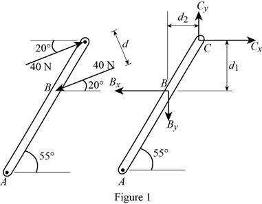
Calculate the vertical height of BC
Substitute 270 mm for y and
Calculate the horizontal height of BC
Substitute 270 mm for y and
Calculate the horizontal reaction at C
Substitute 40 N for
Calculate the vertical reaction at C
Substitute 40 N for
Find the moment of the couple (M):
Take the moment about B.
Substitute 0.22117 m for
Thus, the moment of the couple (M) formed by two forces by resolving each force into horizontal and vertical components and adding the moments of the two resulting couples is
(b)
The moment of the couple (M) formed by two forces by using the perpendicular distance between the two forces.
(b)
Answer to Problem 3.71P
The moment of the couple (M) formed by two forces by using the perpendicular distance between the two forces is
Explanation of Solution
Given information:
The applied force at point B
The applied force at point C
The length of AB (x) is 390 mm.
The length of BC (y) is 270 mm.
The angle of the inclined lever
The angle of the force acting at point C
Calculation:
Calculate the distance (d) between the two forces using the relation:
Substitute 270 mm for y,
Calculate the moment of the couple (M) formed by two forces by using the perpendicular distance between the two forces using the relation:
Substitute 40 N for F and 0.154866 m for d.
Thus, the moment of the couple (M) formed by two forces by using the perpendicular distance between the two forces is
(c)
The moment of the couple (M) formed by summing the moments of two forces about point A.
(c)
Answer to Problem 3.71P
The moment of the couple (M) formed by summing the moments of two forces about point A is
Explanation of Solution
Given information:
The applied force at point B
The applied force at point C
The length of AB (x) is 390 mm.
The length of BC (y) is 270 mm.
The angle of the inclined lever
The angle of the force acting at point C
Calculation:
Calculate the position vector of from point B to point A
Substitute 390 mm for x and
Calculate the force at B by resolving in horizontal and vertical direction using the relation:
Substitute 40 N for
Calculate the position vector of from point C to point A
Substitute 390 mm for x, 270 mm for y and
Calculate the force at C by resolving in horizontal and vertical direction using the relation:
Substitute 40 N for
Calculate the moment of the couple (M) formed by summing the moments of two forces about point A using the relation:
Take the moment about A.
Substitute
Thus, the moment of the couple (M) formed by summing the moments of two forces about point A is
Want to see more full solutions like this?
Chapter 3 Solutions
VECTOR MECH...,STAT.+DYNA.(LL)-W/ACCESS


- Auto Controls Hand sketch the root Focus of the following transfer function How many asymptotes are there ?what are the angles of the asymptotes?Does the system remain stable for all values of K NO COPIED SOLUTIONSarrow_forward-400" 150" in Datum 80" 90" -280"arrow_forwardUsing hand drawing both of themarrow_forward
- A 10-kg box is pulled along P,Na rough surface by a force P, as shown in thefigure. The pulling force linearly increaseswith time, while the particle is motionless att = 0s untilit reaches a maximum force of100 Nattimet = 4s. If the ground has staticand kinetic friction coefficients of u, = 0.6 andHU, = 0.4 respectively, determine the velocityof the A 1 0 - kg box is pulled along P , N a rough surface by a force P , as shown in the figure. The pulling force linearly increases with time, while the particle is motionless at t = 0 s untilit reaches a maximum force of 1 0 0 Nattimet = 4 s . If the ground has static and kinetic friction coefficients of u , = 0 . 6 and HU , = 0 . 4 respectively, determine the velocity of the particle att = 4 s .arrow_forwardCalculate the speed of the driven member with the following conditions: Diameter of the motor pulley: 4 in Diameter of the driven pulley: 12 in Speed of the motor pulley: 1800 rpmarrow_forward4. In the figure, shaft A made of AISI 1010 hot-rolled steel, is welded to a fixed support and is subjected to loading by equal and opposite Forces F via shaft B. Stress concentration factors K₁ (1.7) and Kts (1.6) are induced by the 3mm fillet. Notch sensitivities are q₁=0.9 and qts=1. The length of shaft A from the fixed support to the connection at shaft B is 1m. The load F cycles from 0.5 to 2kN and a static load P is 100N. For shaft A, find the factor of safety (for infinite life) using the modified Goodman fatigue failure criterion. 3 mm fillet Shaft A 20 mm 25 mm Shaft B 25 mmarrow_forward
 Elements Of ElectromagneticsMechanical EngineeringISBN:9780190698614Author:Sadiku, Matthew N. O.Publisher:Oxford University Press
 Mechanics of Materials (10th Edition)Mechanical EngineeringISBN:9780134319650Author:Russell C. HibbelerPublisher:PEARSON
 Thermodynamics: An Engineering ApproachMechanical EngineeringISBN:9781259822674Author:Yunus A. Cengel Dr., Michael A. BolesPublisher:McGraw-Hill Education
 Control Systems EngineeringMechanical EngineeringISBN:9781118170519Author:Norman S. NisePublisher:WILEY
 Mechanics of Materials (MindTap Course List)Mechanical EngineeringISBN:9781337093347Author:Barry J. Goodno, James M. GerePublisher:Cengage Learning
 Engineering Mechanics: StaticsMechanical EngineeringISBN:9781118807330Author:James L. Meriam, L. G. Kraige, J. N. BoltonPublisher:WILEY