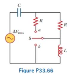
A capacitor, a coil, and two resistors of equal resistance are arranged in an AC circuit as shown in Figure P33.66 (page 1028). An AC source provides an emf of ΔVrms = 20.0 V at a frequency of 60.0 Hz. When the double throw switch S is open as shown in the figure, the rms current is 183 mA. When the switch is closed in position a, the rms current is 298 mA. When the switch is closed in position b, the rms current is 137 mA. Determine the values of (a) R, (b) C, and (c) L. (d) Is more than one set of values possible? Explain.

(a)
The value of resistance.
Answer to Problem 33.66AP
The value of resistance is
Explanation of Solution
Given info: The value of the source emf is
The expression for inductive reactance is,
Here,
The expression for capacitive reactance is,
Here,
The expression for the impedance of the circuit is.
Here,
The expression of the impedance in terms of voltage and current is,
Here,
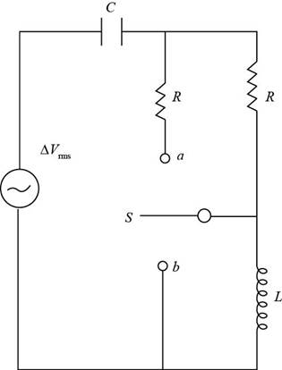
The figure below depicts the circuit when the switch is in open condition.

Figure (1)
From figure(1), for the throw switch in open condition:
Substitute
Substitute
For the throw switch at a position:
The two resistances are in parallel.
The expression of the equivalent resistance is.
Substitute
Substitute
Subtract equation (2) from equation (1).
Conclusion:
Therefore, the value of resistance is
(b)
The value of the capacitance.
Answer to Problem 33.66AP
The value of the capacitance is
Explanation of Solution
Given info: The value of the source emf is
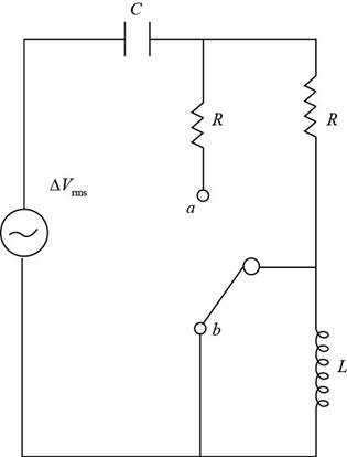
The figure below depicts the circuit when switch is at position b.

Figure (2)
From figure (2), for the throw switch at b position:
When the switch is at position b the inductor gets short circuited.
Substitute
Rearrange the above expression for value of
Substitute
Substitute
Rearrange the above equation for value of value of
Substitute
Conclusion:
Therefore, the value of the capacitance is
(c)
The value of the inductance.
Answer to Problem 33.66AP
The values of the inductance are
Explanation of Solution
Given info: The value of the source emf is
Substitute
For first value of the inductor,
Substitute
Substitute
Thus, the first value of the inductor is
For second value of the inductor,
Substitute
Substitute  for f in the above expression.
Thus, the second value of the inductor is
Conclusion:
Therefore, the values of the inductance are
(d)
Whether more than one set of value possible.
Answer to Problem 33.66AP
The resistance and capacitance has one set of values, the inductor has in two set of values.
Explanation of Solution
Given info: : The value of the source emf is
From the calculation in part (a),(b) and (c),
The value of resistance is
The value of capacitance is
The values of the inductor are
Hence the resistance and the capacitance has one value while the inductor has two set of value in the circuit.
Conclusion:
Therefore, the resistance and capacitance has one set of values, the inductor has in two set of values.
Want to see more full solutions like this?
Chapter 33 Solutions
Physics for Scientists and Engineers, Volume 1, Chapters 1-22
- How can i solve this if n1 (refractive index of gas) and n2 (refractive index of plastic) is not known. And the brewsters angle isn't knownarrow_forward2. Consider the situation described in problem 1 where light emerges horizontally from ground level. Take k = 0.0020 m' and no = 1.0001 and find at which horizontal distance, x, the ray reaches a height of y = 1.5 m.arrow_forward2-3. Consider the situation of the reflection of a pulse at the interface of two string described in the previous problem. In addition to the net disturbances being equal at the junction, the slope of the net disturbances must also be equal at the junction at all times. Given that p1 = 4.0 g/m, H2 = 9.0 g/m and Aj = 0.50 cm find 2. A, (Answer: -0.10 cm) and 3. Ay. (Answer: 0.40 cm)please I need to show all work step by step problems 2 and 3arrow_forward
- look at answer show all work step by steparrow_forwardLook at the answer and please show all work step by steparrow_forward3. As a woman, who's eyes are h = 1.5 m above the ground, looks down the road sees a tree with height H = 9.0 m. Below the tree is what appears to be a reflection of the tree. The observation of this apparent reflection gives the illusion of water on the roadway. This effect is commonly called a mirage. Use the results of questions 1 and 2 and the principle of ray reversibility to analyze the diagram below. Assume that light leaving the top of the tree bends toward the horizontal until it just grazes ground level. After that, the ray bends upward eventually reaching the woman's eyes. The woman interprets this incoming light as if it came from an image of the tree. Determine the size, H', of the image. (Answer 8.8 m) please show all work step by steparrow_forward
 Physics for Scientists and Engineers, Technology ...PhysicsISBN:9781305116399Author:Raymond A. Serway, John W. JewettPublisher:Cengage Learning
 Physics for Scientists and Engineers: Foundations...PhysicsISBN:9781133939146Author:Katz, Debora M.Publisher:Cengage Learning
 Physics for Scientists and EngineersPhysicsISBN:9781337553278Author:Raymond A. Serway, John W. JewettPublisher:Cengage Learning
 Physics for Scientists and Engineers with Modern ...PhysicsISBN:9781337553292Author:Raymond A. Serway, John W. JewettPublisher:Cengage Learning
 College PhysicsPhysicsISBN:9781305952300Author:Raymond A. Serway, Chris VuillePublisher:Cengage Learning


