Concept explainers
Videos
(a)
The distance between the object and the final image.
(a)
Explanation of Solution
Given:
The distance of an object is
The focal length of the lens is
The focal length of a second lens is
The distance of the second lens is
Formula used:
Draw a ray diagram to show the image distance and its properties.
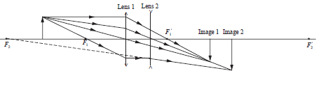
Write the expression for the thin lens equation for the first lens.
Here,
Rearrange the above equation to calculate the image distance for first lens.
Write the expression for the thin lens equation for the second lens.
Here,
Rearrange the above equation to calculate the image distance for second lens.
Write the expression for the object distance for second lens.
Here,
Write the expression for object to image distance.
Here,
Calculation:
Substitute
Substitute
Substitute
Substitute
Conclusion:
Thus, the object to the final image distance is
(b)
The overall magnification of the system.
(b)
Explanation of Solution
Given:
The object distance for the first lens is
The image distance for the first lens is
The object distance for the second lens is
The image distance for the second lens is
Formula used:
Write the expression for the lateral magnification of the image formed by the first lens.
Here,
Write the expression for the lateral magnification of the image formed by the second lens.
Here,
Write the expression for the overall magnification for a system of two lenses.
Here,
Substitute
Calculation:
Substitute
Conclusion:
Thus, the overall magnification is
(c)
Whether the object is real or virtual and upright or inverted.
(c)
Explanation of Solution
Given:
The final image distance from the second lens is
The overall magnification for the system of two lenses is
Introduction:
A real image is formed by an object when all the outgoing parallel rays from the object are appeared to converge to a point. For positive image distance the image is real and for negative image distance the image is virtual.
The image distance,
Conclusion:
Thus, the image is real and inverted.
Want to see more full solutions like this?
Chapter 32 Solutions
PHYSICS F/SCI.+ENGRS.,STAND.-W/ACCESS


- A long, straight wire carries a current of 10 A along what we’ll define to the be x-axis. A square loopin the x-y plane with side length 0.1 m is placed near the wire such that its closest side is parallel tothe wire and 0.05 m away.• Calculate the magnetic flux through the loop using Ampere’s law.arrow_forwardDescribe the motion of a charged particle entering a uniform magnetic field at an angle to the fieldlines. Include a diagram showing the velocity vector, magnetic field lines, and the path of the particle.arrow_forwardDiscuss the differences between the Biot-Savart law and Coulomb’s law in terms of their applicationsand the physical quantities they describe.arrow_forward
- Explain why Ampere’s law can be used to find the magnetic field inside a solenoid but not outside.arrow_forward3. An Atwood machine consists of two masses, mA and m B, which are connected by an inelastic cord of negligible mass that passes over a pulley. If the pulley has radius RO and moment of inertia I about its axle, determine the acceleration of the masses mA and m B, and compare to the situation where the moment of inertia of the pulley is ignored. Ignore friction at the axle O. Use angular momentum and torque in this solutionarrow_forwardA 0.850-m-long metal bar is pulled to the right at a steady 5.0 m/s perpendicular to a uniform, 0.650-T magnetic field. The bar rides on parallel metal rails connected through a 25-Ω, resistor (Figure 1), so the apparatus makes a complete circuit. Ignore the resistance of the bar and the rails. Please explain how to find the direction of the induced current.arrow_forward
- For each of the actions depicted, determine the direction (right, left, or zero) of the current induced to flow through the resistor in the circuit containing the secondary coil. The coils are wrapped around a plastic core. Immediately after the switch is closed, as shown in the figure, (Figure 1) in which direction does the current flow through the resistor? If the switch is then opened, as shown in the figure, in which direction does the current flow through the resistor? I have the answers to the question, but would like to understand the logic behind the answers. Please show steps.arrow_forwardWhen violet light of wavelength 415 nm falls on a single slit, it creates a central diffraction peak that is 8.60 cm wide on a screen that is 2.80 m away. Part A How wide is the slit? ΟΙ ΑΣΦ ? D= 2.7.10-8 Submit Previous Answers Request Answer × Incorrect; Try Again; 8 attempts remaining marrow_forwardTwo complex values are z1=8 + 8i, z2=15 + 7 i. z1∗ and z2∗ are the complex conjugate values. Any complex value can be expessed in the form of a+bi=reiθ. Find θ for (z1-z∗2)/z1+z2∗. Find r and θ for (z1−z2∗)z1z2∗ Please show all stepsarrow_forward
- Calculate the center of mass of the hollow cone shown below. Clearly specify the origin and the coordinate system you are using. Z r Y h Xarrow_forward12. If all three collisions in the figure below are totally inelastic, which will cause more damage? (think about which collision has a larger amount of kinetic energy dissipated/lost to the environment? I m II III A. I B. II C. III m m v brick wall ע ע 0.5v 2v 0.5m D. I and II E. II and III F. I and III G. I, II and III (all of them) 2marrow_forwardCan you solve this 2 question teach me step by step and draw for mearrow_forward
 Physics for Scientists and Engineers: Foundations...PhysicsISBN:9781133939146Author:Katz, Debora M.Publisher:Cengage Learning
 Principles of Physics: A Calculus-Based TextPhysicsISBN:9781133104261Author:Raymond A. Serway, John W. JewettPublisher:Cengage Learning
 University Physics Volume 3PhysicsISBN:9781938168185Author:William Moebs, Jeff SannyPublisher:OpenStax
 Physics for Scientists and Engineers, Technology ...PhysicsISBN:9781305116399Author:Raymond A. Serway, John W. JewettPublisher:Cengage Learning
 Physics for Scientists and EngineersPhysicsISBN:9781337553278Author:Raymond A. Serway, John W. JewettPublisher:Cengage Learning
 Physics for Scientists and Engineers with Modern ...PhysicsISBN:9781337553292Author:Raymond A. Serway, John W. JewettPublisher:Cengage Learning