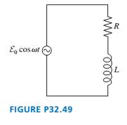
Use a phasor diagram to analyze the RL circuit of FIGURE P32.49. In particular,
a. Find expressions for I,
b. What is
c. If the output is taken from the resistor, is this a low-pass or a
high-pass filter? Explain.
d. Find an expression for the crossover frequency

Want to see the full answer?
Check out a sample textbook solution
Chapter 32 Solutions
Physics for Scientists and Engineers: A Strategic Approach with Modern Physics (Chs 1-42) Plus Mastering Physics with Pearson eText -- Access Card Package (4th Edition)
- No chatgpt pls will upvotearrow_forwardair is pushed steadily though a forced air pipe at a steady speed of 4.0 m/s. the pipe measures 56 cm by 22 cm. how fast will air move though a narrower portion of the pipe that is also rectangular and measures 32 cm by 22 cmarrow_forwardNo chatgpt pls will upvotearrow_forward
- 13.87 ... Interplanetary Navigation. The most efficient way to send a spacecraft from the earth to another planet is by using a Hohmann transfer orbit (Fig. P13.87). If the orbits of the departure and destination planets are circular, the Hohmann transfer orbit is an elliptical orbit whose perihelion and aphelion are tangent to the orbits of the two planets. The rockets are fired briefly at the depar- ture planet to put the spacecraft into the transfer orbit; the spacecraft then coasts until it reaches the destination planet. The rockets are then fired again to put the spacecraft into the same orbit about the sun as the destination planet. (a) For a flight from earth to Mars, in what direction must the rockets be fired at the earth and at Mars: in the direction of motion, or opposite the direction of motion? What about for a flight from Mars to the earth? (b) How long does a one- way trip from the the earth to Mars take, between the firings of the rockets? (c) To reach Mars from the…arrow_forwardNo chatgpt pls will upvotearrow_forwarda cubic foot of argon at 20 degrees celsius is isentropically compressed from 1 atm to 425 KPa. What is the new temperature and density?arrow_forward
- Calculate the variance of the calculated accelerations. The free fall height was 1753 mm. The measured release and catch times were: 222.22 800.00 61.11 641.67 0.00 588.89 11.11 588.89 8.33 588.89 11.11 588.89 5.56 586.11 2.78 583.33 Give in the answer window the calculated repeated experiment variance in m/s2.arrow_forwardNo chatgpt pls will upvotearrow_forwardCan you help me solve the questions pleasearrow_forward
- Can you help me solve these questions please so i can see how to do itarrow_forwardHow can i solve this if n1 (refractive index of gas) and n2 (refractive index of plastic) is not known. And the brewsters angle isn't knownarrow_forward2. Consider the situation described in problem 1 where light emerges horizontally from ground level. Take k = 0.0020 m' and no = 1.0001 and find at which horizontal distance, x, the ray reaches a height of y = 1.5 m.arrow_forward

 Physics for Scientists and Engineers: Foundations...PhysicsISBN:9781133939146Author:Katz, Debora M.Publisher:Cengage Learning
 College PhysicsPhysicsISBN:9781938168000Author:Paul Peter Urone, Roger HinrichsPublisher:OpenStax College
 College PhysicsPhysicsISBN:9781305952300Author:Raymond A. Serway, Chris VuillePublisher:Cengage Learning
 College PhysicsPhysicsISBN:9781285737027Author:Raymond A. Serway, Chris VuillePublisher:Cengage Learning
 Physics for Scientists and Engineers, Technology ...PhysicsISBN:9781305116399Author:Raymond A. Serway, John W. JewettPublisher:Cengage Learning


