
Concept explainers
Videos
Perform the same computation as in Sec. 32.1, but use
To calculate: The concentration of the distributed-parameter system equations for
Answer to Problem 1P
Solution: The concentration of equations for
Explanation of Solution
Given Information:
The distributed-parameter system depicts chemical modelling being subjected to first order decay and the tank is mixed well vertically and laterally.
Apply finite length of segment,
Here,
is the volume,
is the flow rate,
is the concentration,
is the dispersion coefficient,
is the tank’s cross-sectional area, and
is the first order decay coefficient.
Calculation:
Substitute centred finite differences for the first and the second derivatives in equation (1) to develop steady-state solution,
Further simplify the equation,
And,
Also,
Solve the equation (2),
Substitute
Hence, the required first equation is
Solve the equation (3),
Substitute
Hence, the required middle equation is
Substitute
in middle equation,
Substitute
Substitute
Substitute
Substitute
in middle equation,
Substitute
in middle equation,
Substitute
in middle equation,
Substitute
in middle equation,
Solve equation (4) for last equation,
Substitute
Hence, the required last equation is
Write all the equations in matrix form,
Express the matrix in tri-diagonal form,
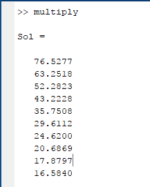
Use MATLAB to solve the above matrix.
The output of the program is given below.
Want to see more full solutions like this?
Chapter 32 Solutions
Numerical Methods For Engineers, 7 Ed


- Detailed report without CHATGPT, accept if you can give with code and plots, previous reported . Do not waste my question.arrow_forwardPlease do not give inappropriate solutions, previous question reported, i need correct report solution for this, NO CHATGPTarrow_forwardNeed detailed report without CHATGPT, accept if you can give with code and plots, previous reported Plots are required.arrow_forward
- Need detailed report without CHATGPT, accept if you can give with code and plots, previous reportedarrow_forward1. Which set of parametric equations is shown in the graph below? Explain your reasoning. a) x = t; y = t² b) x = = t²; y = t -3-2-1 5 4 3 2 1 12 3 2. Using the graph of f, a. determine whether dy/dt is positive or negative given that dx/dt is negative and b. determine whether dx/dt is positive or negative given that dy/dt is positive. Explain your reasoning. 2 f x 1 2 3 4arrow_forwardFind the perimeter of the triangle. Express the perimeter using the same unit of measure that appears on the given sides. 9 ft 13 ft 6 ft The perimeter isarrow_forward
- Use the formula for Pr to evaluate the following expression. 9P5 9P5 =☐arrow_forwardFind the volume of the figure. The volume of the figure is 3 m 3 m 3 marrow_forwardFind the circumference and area of the circle. Express answers in terms of and then round to the nearest tenth. Find the circumference in terms of C= (Type an exact answer in terms of x.) Find the circumference rounded to the nearest tenth. C= Find the area in terms of A= (Type an exact answer in terms of x.) Find the area rounded to the nearest tenth. A= 10 cmarrow_forward
- In Exercises 62-64, sketch a reasonable graph that models the given situation. The number of hours of daylight per day in your hometown over a two-year period The motion of a diving board vibrating 10 inches in each direction per second just after someone has dived off The distance of a rotating beam of light from a point on a wallarrow_forwardThe manager of a fleet of automobiles is testing two brands of radial tires and assigns one tire of each brand at random to the two rear wheels of eight cars and runs the cars until the tires wear out. The data (in kilometers) follow. CAR BRAND1 BRAND2 DIFFERENCE = (BRAND1 - BF 1 36,925 33,018 3,907 2 45,300 43,280 2,020 3 36,240 35,500 740 4 32,100 31,200 900 5 37,210 37,015 195 6 48,360 46,800 1,560 7 38,200 37,810 390 8 33,500 33,215 285arrow_forwardDiabetes and obesity are serious health concerns in the United States and much of the developed world. Measuring the amount of body fat a person carries is one way to monitor weight control progress, but measuring it accurately involves either expensive X-ray equipment or a pool in which to dunk the subject. Instead body mass index (BMI) is often used as a proxy for body fat because it is easy to measure: BMI = mass(kg)/(height(m))² = 703 mass(lb)/(height(in))². In a study of 15 men at TXST, both BMI and body fat were measured. Researchers imported the data into statistical software for analysis. A few values are missing from the output. Complete the table by filling in the missing values. Model Summary S R-sq % (three decimal places) (two decimal places. e.g. 12.3456%, enter 12.35) Analysis of Variance Source Model Error Total DF SS MS F P 17.600 0.001 DF: whole numbers SS or MS; three decimal places 34.810 Does a simple linear regression model seem reasonable in this situation?…arrow_forward
 Algebra & Trigonometry with Analytic GeometryAlgebraISBN:9781133382119Author:SwokowskiPublisher:Cengage
 Algebra: Structure And Method, Book 1AlgebraISBN:9780395977224Author:Richard G. Brown, Mary P. Dolciani, Robert H. Sorgenfrey, William L. ColePublisher:McDougal Littell