Videos
(a)
The maximum emf induced between the ends of the conductor.
(a)
Answer to Problem 46P
The maximum emf induced between the ends of the conductor is
Explanation of Solution
Write the expression to obtain the magnetic flux.
Here,
Write the expression to obtain the induced emf between the ends of the conductor.
Here,
Substitute
Substitute
Here,
For maximum induced emf between the ends of the conductor,
Substitute
Conclusion:
Substitute
Therefore, the maximum emf induced between the ends of the conductor is
(b)
The value of the average induced emf for each complete rotation.
(b)
Answer to Problem 46P
The value of the average induced emf for each complete rotation is
Explanation of Solution
Write the expression to obtain the average induced emf for each complete rotation.
Here,
Conclusion:
Substitute
Therefore, the value of the average induced emf for each complete rotation is
(c)
The variation in answers in part (a) and (b) when change in magnetic field is allowed to extent a distance
(c)
Answer to Problem 46P
The answer in part (a) and (b) would be doubled when change in magnetic field is allowed to extent a distance
Explanation of Solution
Consider equation (I).
Substitute
Conclusion:
Substitute
Thus, the maximum emf induced between the ends of the conductor is
Substitute
Thus, the value of the average induced emf for each complete rotation is
Therefore, the answer in part (a) and (b) would be doubled when change in magnetic field is allowed to extent a distance
(d)
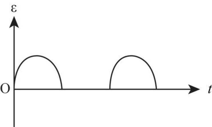
The graph between emf versus time when the magnetic field is drawn as shown in the figure P31.46.
(d)
Answer to Problem 46P
The graph between emf versus time is as shown below.
Explanation of Solution
When change in magnetic field is not allowed to extent a distance
Thus, the emf is only in the coil for the half rotation and for the other half rotation, there is no induced emf in the coil.
The graph between emf versus time is as shown below.

Figure-(1)
(d)
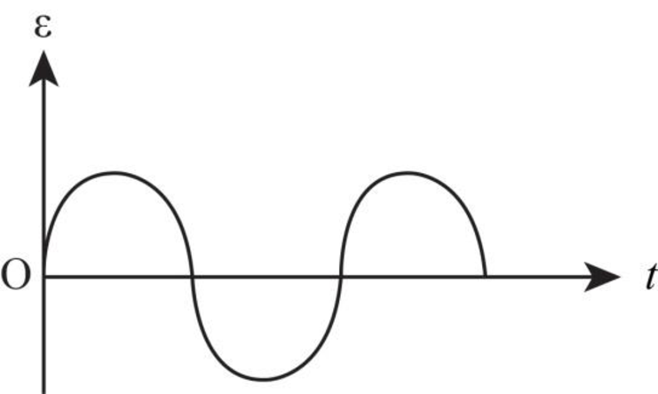
The graph between emf versus time when the magnetic field is extended as described in part (c).
(d)
Answer to Problem 46P
The graph between emf versus time is as shown in the figure below.
Explanation of Solution
When the change in magnetic field is allowed to extent a distance
Thus, the emf is induced in the coil in the whole rotation of the coil.
The graph for this case is as shown in the figure below.

Figure-(2)
Want to see more full solutions like this?
Chapter 31 Solutions
Physics for Scientists and Engineers With Modern Physics


- (a) For a spherical capacitor with inner radius a and outer radius b, we have the following for the capacitance. ab C = k₂(b- a) 0.0695 m 0.145 m (8.99 × 10º N · m²/c²)( [0.145 m- 0.0695 m × 10-11 F = PF IIarrow_forwardA pendulum bob A (0.5 kg) is given an initialspeed of vA = 4 m/s when the chord ishorizontal. It then hits a stationary block B (1kg) which then slides to a maximum distanced before it stops. Determine the value of d.The coefficient of static friction between theblock and the plane is μk = 0.2. The coefficientof restitution between A and B is e = 0.8.Ans: d=1.0034 marrow_forwardFigure 29-43 Problem 12. ••13 In Fig. 29-44, point P₁ is at distance R = 13.1 cm on the perpendicular bisector of a straight wire of length L = 18.0 cm carrying current i = 58.2 mA. (Note that the wire is not long.) What is the magnitude of the magnetic field at P₁ due to i? P2° R R Larrow_forward
- Checkpoint 1 The figure shows the current i in a single-loop circuit with a battery B and a resistance R (and wires of neg- ligible resistance). (a) Should the emf arrow at B be drawn pointing leftward or rightward? At points a, B C R b, and c, rank (b) the magnitude of the current, (c) the electric potential, and (d) the electric potential energy of the charge carriers, greatest first.arrow_forwardPls help ASAParrow_forwardPls help asaparrow_forward
- Pls help asaparrow_forward3. If the force of gravity stopped acting on the planets in our solar system, what would happen? a) They would spiral slowly towards the sun. b) They would continue in straight lines tangent to their orbits. c) They would continue to orbit the sun. d) They would fly straight away from the sun. e) They would spiral slowly away from the sun. 4. 1 The free-body diagram of a wagon being pulled along a horizontal surface is best represented by A F N B C 0 Ꭰ FN E a) A b) B c) C app app The app 10 app d) e) ס ח D E 10 apparrow_forwardPls help ASAParrow_forward
 Principles of Physics: A Calculus-Based TextPhysicsISBN:9781133104261Author:Raymond A. Serway, John W. JewettPublisher:Cengage Learning
 Physics for Scientists and Engineers: Foundations...PhysicsISBN:9781133939146Author:Katz, Debora M.Publisher:Cengage Learning
 Physics for Scientists and Engineers, Technology ...PhysicsISBN:9781305116399Author:Raymond A. Serway, John W. JewettPublisher:Cengage Learning
 College PhysicsPhysicsISBN:9781938168000Author:Paul Peter Urone, Roger HinrichsPublisher:OpenStax College
 Physics for Scientists and EngineersPhysicsISBN:9781337553278Author:Raymond A. Serway, John W. JewettPublisher:Cengage Learning