
Concept explainers
Calculate the value of
Answer to Problem 91P
The value of
Explanation of Solution
Given data:
Refer Figure 3.127 in the textbook for the transistor circuit.
The common-emitter current gain
The base-emitter voltage
Formula used:
Write the expression for collector current in transistor.
Here,
Write the expression for emitter current of transistor.
Calculation:
The Thevenin resistance of the input circuit is the parallel combination of
The Thevenin voltage of the input circuit is the voltage across
Modify the Figure 3.127 with the incorporation of Thevenin equivalent circuit as shown in Figure 1.
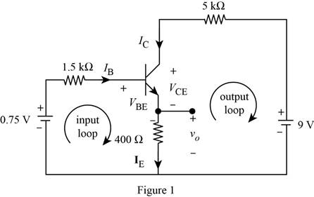
Apply Kirchhoff’s voltage law to input loop in Figure 1.
Substitute equation (2) in (3).
Substitute
Simplify the above equation as follows.
From Figure 1, write the expression for voltage
Substitute equation (2) in (4).
Substitute
Apply Kirchhoff’s voltage law to output loop in Figure 1.
Substitute equation (1) in (6).
Substitute
Conclusion:
Therefore, the value of
Want to see more full solutions like this?
Chapter 3 Solutions
EE 98: Fundamentals of Electrical Circuits - With Connect Access


- Using the table below, design a third (3th) order Butterworth HPF with a 4 KHz cutoff frequency. What is the additional stage required to HPF to design a third order BPF. Explain your answe Order Stage poles DF 2 stage poles 3 stage DF poles DF 1 1 Optional 2 1.414 3 י 1 1 2 1.848 2 0.765 5 2 1 1.618 1 0.618 6 2 1.932 1.414 2 0.518arrow_forward.I need the correct answer, and if it's wrong, please fix it 7. The midrange voltage gain of an amplifier is 100. The input RC circuit has a lower critical frequency of 1 kHz. The actual voltage gain at f-100 Hz is 100. 10. In a high-pass filter, the roll-off region occurs above the critical frequency.arrow_forwardSolve this problem and show all of the workarrow_forward
- Don't use ai to answer I will report you answerarrow_forwardDon't use ai to answer I will report you answerarrow_forwardQ3/A unity-feedback system with the forward transfer function G(S)= K S(S+7) is operating with a closed-loop step response that has 15% overshoot. Do the following: a. Evaluate the steady-state error for a unit ramp input. b. Design a lag compensator to improve the steady-state error by a factor of 20 to get a new dominant closed-loop poles S-3.4+ j5.63. place the pole of the lag compensator at s=-0.01 c. Design a lag compensator using OP amp if R1= 100KS2 R2=10 KS2 and R3= 10Karrow_forward
- Q2: (33 Marks) Design FBD for manufacturing system where a conveyor belt is used to move a cart through a tunnel for processing. The process begins when a worker presses a start push button located at the start of the conveyor. Once the start push button is pressed, the cart moves forward along the conveyor belt and enters the tunnel. When the cart reaches the end of the tunnel, it stops automatically and remains in place for 10-minutes to complete a required operation, such as cooling or drying. After the 10-minute delay, the cart automatically returns to the starting point where the worker is stationed. The system then waits for the worker to press the start push button again, at which point the process is repeated. Start PBO Stop PBO LSI 0 LS 2 Motorarrow_forward1. Find the resolution, current and output voltage for a binary weighted resistor DAC of (applied binary word is (locoj), the resistor values R = 12 kQ, Rf = 6 k2 and VR = 12 V. 2. Convert the following 5-bit digital values (ble 10) to analog, using the R-2R ladder. Assume that the Vs = 10 V, R = Rf = 7 ksarrow_forwardK Q4/ For the unity-feedback system where G(s) = do the following: a. Plot the Nyquist diagram. (S+2)(S+4)(S+6) b. Use your Nyquist diagram to find the range of gain, K, for stabilityarrow_forward
 Introductory Circuit Analysis (13th Edition)Electrical EngineeringISBN:9780133923605Author:Robert L. BoylestadPublisher:PEARSON
 Delmar's Standard Textbook Of ElectricityElectrical EngineeringISBN:9781337900348Author:Stephen L. HermanPublisher:Cengage Learning
 Programmable Logic ControllersElectrical EngineeringISBN:9780073373843Author:Frank D. PetruzellaPublisher:McGraw-Hill Education
 Fundamentals of Electric CircuitsElectrical EngineeringISBN:9780078028229Author:Charles K Alexander, Matthew SadikuPublisher:McGraw-Hill Education
 Electric Circuits. (11th Edition)Electrical EngineeringISBN:9780134746968Author:James W. Nilsson, Susan RiedelPublisher:PEARSON
 Engineering ElectromagneticsElectrical EngineeringISBN:9780078028151Author:Hayt, William H. (william Hart), Jr, BUCK, John A.Publisher:Mcgraw-hill Education,