
Basic Engineering Circuit Analysis
11th Edition
ISBN: 9781118992661
Author: Irwin, J. David, NELMS, R. M., 1939-
Publisher: Wiley,
expand_more
expand_more
format_list_bulleted
Concept explainers
Videos
Textbook Question
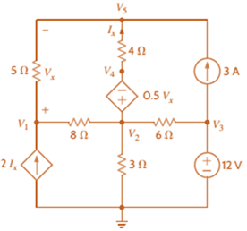
Chapter 3, Problem 63P
Use nodal analysis to determine the node voltages defined in the circuit in Fig. P3.63.
Expert Solution & Answer
Want to see the full answer?
Check out a sample textbook solution
Students have asked these similar questions
Please solve this question step by step and handwritten and do not use chat gpt or ai tools thank you very much!
Please solve question c,d,e step by step and handwritten and do not use chat gpt or ai tools thank you very much!
Q1: Design a logic circuit for the finite-state machine described by the assigned
table in Fig. 1:
Using D flip-flops.
a.
b.
Using T flip-flops.
Present
Next State
Output
State
x=0
x=0
YE
Y₁Y
Y₁Y
Z
00
00
01
0
0
от
00
0
0
10
00
10
11
00
10
0
Chapter 3 Solutions
Basic Engineering Circuit Analysis
Ch. 3 - Use nodal analysis to find V1 in the circuit in...Ch. 3 - Find both Io and Vo in the network in Fig. P3.2...Ch. 3 - Find I1 in the network in Fig. P3.3.Ch. 3 - Find I1 in the circuit in Fig. P3.4.Ch. 3 - Use nodal analysis to find V1 in the circuit in...Ch. 3 - Find V1 and V2 in the circuit in Fig. P3.6 using...Ch. 3 - Use nodal analysis to find both V1 and Vo in the...Ch. 3 - Write the node equations for the circuit in Fig....Ch. 3 - Find Vo in the network in Fig. P3.9.Ch. 3 - Find Io in the circuit in Fig. P3.10 using nodal...
Ch. 3 - Use nodal analysis to find Io in the network in...Ch. 3 - Use nodal analysis to find Vo in the circuit in...Ch. 3 - Find Vo in the network in Fig. P3.13 using nodal...Ch. 3 - Use nodal analysis to find Vo in the circuit in...Ch. 3 - Find Io in the network in Fig. P3.15 using nodal...Ch. 3 - Use nodal analysis to find Vo in the circuit in...Ch. 3 - Use nodal analysis to find Vo in the network in...Ch. 3 - Use nodal analysis to find Vo in the circuit in...Ch. 3 - Find Vo in the circuit in Fig. P3.19 using...Ch. 3 - Find Vo in the network in Fig. P3.20 using nodal...Ch. 3 - Find Vo in the network in Fig. P3.21 using nodal...Ch. 3 - Find Io in the circuit in Fig. P3.22 using nodal...Ch. 3 - Use nodal analysis to determine the node voltages...Ch. 3 - Use nodal analysis to find Vo in the network in...Ch. 3 - Use nodal analysis to find Vo in the circuit in...Ch. 3 - Use nodal analysis to solve for the node voltages...Ch. 3 - Find Vo in the network in Fig. P3.27 using nodal...Ch. 3 - Find Io in the network in Fig. P3.28 using nodal...Ch. 3 - Use nodal analysis to find Io in the circuit in...Ch. 3 - Find Vo in the circuit in Fig. P3.30 using nodal...Ch. 3 - Find Io in the circuit in Fig. P3.31 using nodal...Ch. 3 - Use nodal analysis to find Io in the circuit in...Ch. 3 - Using analysis, find Vo in the network in Fig....Ch. 3 - Find Vo in the network in Fig. P3.34 using nodal...Ch. 3 - Find Vo in the circuit in Fig. P3.35 using nodal...Ch. 3 - Find Vo in the circuit in Fig. P3.36 using nodal...Ch. 3 - Use nodal analysis to find Vo in the circuit in...Ch. 3 - Find Vo in the circuit in Fig. P3.38 using nodal...Ch. 3 - Find Vo in the circuit in Fig. P3.39 using nodal...Ch. 3 - Use nodal analysis to find Vo in the circuit in...Ch. 3 - Find Vo in the network in Fig. P3.41.Ch. 3 - Find I0 in the network in Fig. P3.42 using nodal...Ch. 3 - Find Vo in the network in Fig. P3.43 using nodal...Ch. 3 - Find Io in the network in Fig. P3.44 using nodal...Ch. 3 - Find Vo in the network in Fig. P3.45 using nodal...Ch. 3 - Find Vo in the circuit in Fig. P3.46 using nodal...Ch. 3 - Find Io in the network in Fig. P3.47 using nodal...Ch. 3 - Use nodal analysis to find Vo in the circuit in...Ch. 3 - Find Vo in the network in Fig. P3.49 using nodal...Ch. 3 - Find Vo in the network in Fig. P3.50 using nodal...Ch. 3 - Find Vo in the circuit in Fig. P3.51.Ch. 3 - Use nodal analysis to find Vo in the circuit in...Ch. 3 - Determine Vo in the network in Fig. P3.53 using...Ch. 3 - Use nodal analysis to find Vo in the circuit in...Ch. 3 - Use nodal analysis to find Vo in the circuit in...Ch. 3 - Find Io in the circuit in Fig. B3.56 using nodal...Ch. 3 - Use nodal analysis to solve for IA in the network...Ch. 3 - Use nodal analysis to find Vo in the circuit in...Ch. 3 - Use nodal analysis to find V1,V2,V3, and V4 in the...Ch. 3 - Determine Vo in the network in Fig. P3.60 using...Ch. 3 - Use nodal analysis to find V1,V2,V3, and V4 in the...Ch. 3 - Use nodal analysis to determine the node voltages...Ch. 3 - Use nodal analysis to determine the node voltages...Ch. 3 - Use nodal analysis to determine the node voltages...Ch. 3 - Find Io in the network in Fig. P3.65 using mesh...Ch. 3 - Find Vo in the network in Fig. P3.66 using mesh...Ch. 3 - Find Vo in the network in Fig. P3.67 using mesh...Ch. 3 - Find Io in the circuit in Fig. P3.68 using mesh...Ch. 3 - Use mesh analysis to find Vo in the circuit in...Ch. 3 - Find Io in the circuit in Fig. P3.70 using mesh...Ch. 3 - Use mesh analysis to find Vo in the network in...Ch. 3 - Find Io in the circuit in Fig. P3.72.Ch. 3 - Find Vo in the circuit in Fig. P3.73 using mesh...Ch. 3 - Find Vo in Fig. P3.74 using mesh analysis.Ch. 3 - Use loop analysis to find Vo in the network in...Ch. 3 - Find Io in Fig. P3.76 using mesh analysis.Ch. 3 - Find Vo in the network in Fig. P3.77 using loop...Ch. 3 - Find Io in the circuit in Fig. P3.78 using loop...Ch. 3 - Find Vo in the circuit in Fig. P3.79 using mesh...Ch. 3 - Use mesh analysis to find Vo in the circuit in...Ch. 3 - Use mesh analysis to find Io in the network in...Ch. 3 - Use loop analysis to find Vo in the circuit in...Ch. 3 - Use loop analysis to calculate the power supplied...Ch. 3 - Use loop analysis to find Io and I1 in the network...Ch. 3 - Find Vo in the network in Fig. P3.85 using loop...Ch. 3 - Find Vo in the circuit in Fig. P3.86 using...Ch. 3 - Find Io in network in Fig. P3.87 using loop...Ch. 3 - Find Io in the network in Fig. P3.88 using loop...Ch. 3 - Use loop analysis to find Vo in the circuit in...Ch. 3 - Using loop analysis, find Vo in the network in...Ch. 3 - Find Io in the circuit in Fig. P3.91 using mesh...Ch. 3 - Use analysis to find Io in the network in Fig....Ch. 3 - Using loop analysis, find Io in the circuit in...Ch. 3 - Find the mesh currents in the network in Fig....Ch. 3 - Using loop analysis, find Vo in the circuit in...Ch. 3 - Using loop analysis, find Vo in the network in...Ch. 3 - Find Io in the circuit in Fig. P3.97 using loop...Ch. 3 - Find Io in the network in Fig. P3.98 using loop...Ch. 3 - Find Vo in the circuit in Fig. P3.99 using loop...Ch. 3 - Use nodal analysis to find Vo in Fig. P3.100.Ch. 3 - Find Vo in the circuit in Fig. P3.101 using nodal...Ch. 3 - Use loop analysis to find Vo in the network in...Ch. 3 - Use nodal analysis to find Vo in the network in...Ch. 3 - Find Vo in the network in Fig. P3.104 using nodal...Ch. 3 - Find the power supplied by the 2-A current source...Ch. 3 - Find Io in the network in Fig. P3.106 using nodal...Ch. 3 - Find Vo in the circuit in Fig. P3.107 using loop...Ch. 3 - Use mesh analysis to find Vo in the circuit in...Ch. 3 - Using mesh analysis, find Vo in the circuit in...Ch. 3 - Find Vo in the circuit in Fig. P3.110 using nodal...Ch. 3 - Find Vx in the circuit in Fig. P3.111.Ch. 3 - Find Io in the circuit in Fig. P3.112.Ch. 3 - Write mesh equations for the circuit in Fig....Ch. 3 - Find Ix in the circuit in Fig. P3.114 using loop...Ch. 3 - Solve for the mesh currents defined in the circuit...Ch. 3 - Solve for the assigned mesh currents in the...Ch. 3 - Using the assigned mesh currents shown in Fig....Ch. 3 - Find Vo in the network in Fig. B3.118.Ch. 3 - Using loop analysis, find Vo in the circuit in...Ch. 3 - Using loop analysis, find Vo in the circuit in...Ch. 3 - Using loop analysis, find Vo in the network in...Ch. 3 - Using loop analysis, find Vo in the circuit in...Ch. 3 - Using loop analysis, find Io in the network in...Ch. 3 - Use analysis to find Io in the circuit in Fig....Ch. 3 - Find Vo in the circuit in Fig. P3.125 using loop...Ch. 3 - Using loop analysis, find Io in the circuit in...Ch. 3 - Use mesh analysis to determine the power delivered...Ch. 3 - Use mesh analysis to find the power delivered by...Ch. 3 - Use nodal analysis to find Vo in the circuit in...Ch. 3 - Find Io in the network in Fig. P3.130 using nodal...Ch. 3 - Find Vo in the circuit in Fig. 3PFE-l. a. 3.33 Vc....Ch. 3 - Determine the power dissipated in the 6-ohm...Ch. 3 - Find the current Ix in the 4-ohm resistor in the...Ch. 3 - Determine the voltage Vo in the circuit in Fig....Ch. 3 - What is the voltage V1 in the circuit in Fig....
Knowledge Booster


Learn more about
Need a deep-dive on the concept behind this application? Look no further. Learn more about this topic, electrical-engineering and related others by exploring similar questions and additional content below.Similar questions
- 2. Using the approximate method, hand sketch the Bode plot for the following transfer functions. a) H(s) = 10 b) H(s) (s+1) c) H(s): = 1 = +1 100 1000 (s+1) 10(s+1) d) H(s) = (s+100) (180+1)arrow_forwardQ4: Write VHDL code to implement the finite-state machine described by the state Diagram in Fig. 1. Fig. 1arrow_forward1. Consider the following feedback system. Bode plot of G(s) is shown below. Phase (deg) Magnitude (dB) -50 -100 -150 -200 0 -90 -180 -270 101 System: sys Frequency (rad/s): 0.117 Magnitude (dB): -74 10° K G(s) Bode Diagram System: sys Frequency (rad/s): 36.8 Magnitude (dB): -99.7 System: sys Frequency (rad/s): 20 Magnitude (dB): -89.9 System: sys Frequency (rad/s): 20 Phase (deg): -143 System: sys Frequency (rad/s): 36.8 Phase (deg): -180 101 Frequency (rad/s) a) Determine the range of K for which the closed-loop system is stable. 102 10³ b) If we want the gain margin to be exactly 50 dB, what is value for K we should choose? c) If we want the phase margin to be exactly 37°, what is value of K we should choose? What will be the corresponding rise time (T) for step-input? d) If we want steady-state error of step input to be 0.6, what is value of K we should choose?arrow_forward
- : Write VHDL code to implement the finite-state machine/described by the state Diagram in Fig. 4. X=1 X=0 solo X=1 X=0 $1/1 X=0 X=1 X=1 52/2 $3/3 X=1 Fig. 4 X=1 X=1 56/6 $5/5 X=1 54/4 X=0 X-O X=O 5=0 57/7arrow_forwardQuestions: Q1: Verify that the average power generated equals the average power absorbed using the simulated values in Table 7-2. Q2: Verify that the reactive power generated equals the reactive power absorbed using the simulated values in Table 7-2. Q3: Why it is important to correct the power factor of a load? Q4: Find the ideal value of the capacitor theoretically that will result in unity power factor. Vs pp (V) VRIPP (V) VRLC PP (V) AT (μs) T (us) 8° pf Simulated 14 8.523 7.84 84.850 1000 29.88 0.866 Measured 14 8.523 7.854 82.94 1000 29.85 0.86733 Table 7-2 Power Calculations Pvs (mW) Qvs (mVAR) PRI (MW) Pay (mW) Qt (mVAR) Qc (mYAR) Simulated -12.93 -7.428 9.081 3.855 12.27 -4.84 Calculated -12.936 -7.434 9.083 3.856 12.32 -4.85 Part II: Power Factor Correction Table 7-3 Power Factor Correction AT (us) 0° pf Simulated 0 0 1 Measured 0 0 1arrow_forwardQuestions: Q1: Verify that the average power generated equals the average power absorbed using the simulated values in Table 7-2. Q2: Verify that the reactive power generated equals the reactive power absorbed using the simulated values in Table 7-2. Q3: Why it is important to correct the power factor of a load? Q4: Find the ideal value of the capacitor theoretically that will result in unity power factor. Vs pp (V) VRIPP (V) VRLC PP (V) AT (μs) T (us) 8° pf Simulated 14 8.523 7.84 84.850 1000 29.88 0.866 Measured 14 8.523 7.854 82.94 1000 29.85 0.86733 Table 7-2 Power Calculations Pvs (mW) Qvs (mVAR) PRI (MW) Pay (mW) Qt (mVAR) Qc (mYAR) Simulated -12.93 -7.428 9.081 3.855 12.27 -4.84 Calculated -12.936 -7.434 9.083 3.856 12.32 -4.85 Part II: Power Factor Correction Table 7-3 Power Factor Correction AT (us) 0° pf Simulated 0 0 1 Measured 0 0 1arrow_forward
- electric plants. Prepare the load schedulearrow_forwardelectric plants Draw the column diagram. Calculate the voltage drop. by hand writingarrow_forwardelectric plants. Draw the lighting, socket, telephone, TV, and doorbell installations on the given single-story project with an architectural plan by hand writingarrow_forward
arrow_back_ios
SEE MORE QUESTIONS
arrow_forward_ios
Recommended textbooks for you
 Introductory Circuit Analysis (13th Edition)Electrical EngineeringISBN:9780133923605Author:Robert L. BoylestadPublisher:PEARSON
 Delmar's Standard Textbook Of ElectricityElectrical EngineeringISBN:9781337900348Author:Stephen L. HermanPublisher:Cengage Learning
 Programmable Logic ControllersElectrical EngineeringISBN:9780073373843Author:Frank D. PetruzellaPublisher:McGraw-Hill Education
 Fundamentals of Electric CircuitsElectrical EngineeringISBN:9780078028229Author:Charles K Alexander, Matthew SadikuPublisher:McGraw-Hill Education
 Electric Circuits. (11th Edition)Electrical EngineeringISBN:9780134746968Author:James W. Nilsson, Susan RiedelPublisher:PEARSON
 Engineering ElectromagneticsElectrical EngineeringISBN:9780078028151Author:Hayt, William H. (william Hart), Jr, BUCK, John A.Publisher:Mcgraw-hill Education,
Introductory Circuit Analysis (13th Edition)
Electrical Engineering
ISBN:9780133923605
Author:Robert L. Boylestad
Publisher:PEARSON
Delmar's Standard Textbook Of Electricity
Electrical Engineering
ISBN:9781337900348
Author:Stephen L. Herman
Publisher:Cengage Learning
Programmable Logic Controllers
Electrical Engineering
ISBN:9780073373843
Author:Frank D. Petruzella
Publisher:McGraw-Hill Education
Fundamentals of Electric Circuits
Electrical Engineering
ISBN:9780078028229
Author:Charles K Alexander, Matthew Sadiku
Publisher:McGraw-Hill Education
Electric Circuits. (11th Edition)
Electrical Engineering
ISBN:9780134746968
Author:James W. Nilsson, Susan Riedel
Publisher:PEARSON
Engineering Electromagnetics
Electrical Engineering
ISBN:9780078028151
Author:Hayt, William H. (william Hart), Jr, BUCK, John A.
Publisher:Mcgraw-hill Education,
Nodal Analysis for Circuits Explained; Author: Engineer4Free;https://www.youtube.com/watch?v=f-sbANgw4fo;License: Standard Youtube License