
Concept explainers
Videos
Use nodal analysis to find
The value of voltage
Answer to Problem 1P
The value of voltage
Explanation of Solution
Calculation:
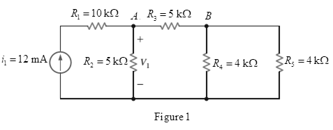
The circuit diagram is redrawn as shown in Figure 1.
Write the expression for KCL at node
Here,
Substitute
Rearrange further.
Write the expression for KCL at node
Here,
Substitute
Rearrange for
Simplify further.
Substitute
Conclusion:
Thus, the value of voltage
Want to see more full solutions like this?
Chapter 3 Solutions
Basic Engineering Circuit Analysis


- Phase (deg) 270 4. Consider a closed-loop system with unity (negative) feedback. The Bode diagram of the open-loop transfer function is given below. Magnitude (dB) -500 -150 -50 10 dB System Frequency (eds): 6.63 Magnitude (B) 0.0778 Буку Frequency(): 10.1 Magnitude ()-705 Frequency(6.63 Phase (deg): -144 Frequency (rad): 10.1 Phase (deg): -180 101 Frequency (rad) a) Find the gain margin, phase margin, gain crossover frequency, and phase crossover frequency. b) Is the closed-loop system stable? What is the steady-state error for step-input?arrow_forwardelectric plantsarrow_forwardsolve and show workarrow_forward
- z+4 What is the value of cz²+2z+5 dz a) If C is the circle |z|=1. c) If C is the circle |z+1+i|=2. b) If C is the circle |z+1-i|=2.arrow_forwardApplication of Complex Inversion Integral for Inverse Z-transform Find Z-1 (z-1)(z-2) }arrow_forwardz+4 What is the value of cz²+2z+5 a) If C is the circle |z|=1. dz b) If C is the circle |z+1-i|=2. c) If C is the circle |z+1+i|=2.arrow_forward
- z+4 What is the value of √cz²+2z+5 dz Sc a) If C is the circle |z|=1. c) If C is the circle |z+1+i|=2. b) If C is the circle |z+1-i|=2.arrow_forwardz+1 What is the value of Sc 73. C -2z² 3-zzz dz i) ii) iii) If C is the circle |z|=1. If C is the circle |z-2-i|=2. If C is the circle |z-1-2i|=2.arrow_forwardApplication of Complex Inversion Integral for Inverse Z-transform Find Z-1 {(2-1)(2+2)}arrow_forward
- 4z Find the residue of f(z) = (z-3)(z+1)²arrow_forwardwhat is the integral of f(z): -3z+4 = around the circle z(z-1)(z-2) |z|=3/2?arrow_forward1. The communication channel bandwidth uses is 25 MHz centered at 1GHz and uses BPSK. The noise power spectral density of the channel is 10^-9 W/Hz. The channel loss between the transmitter and receiver is 25dB. The application requires a BER of less than 10^-4. Determine the minimum transmit power required.arrow_forward
 Introductory Circuit Analysis (13th Edition)Electrical EngineeringISBN:9780133923605Author:Robert L. BoylestadPublisher:PEARSON
 Delmar's Standard Textbook Of ElectricityElectrical EngineeringISBN:9781337900348Author:Stephen L. HermanPublisher:Cengage Learning
 Programmable Logic ControllersElectrical EngineeringISBN:9780073373843Author:Frank D. PetruzellaPublisher:McGraw-Hill Education
 Fundamentals of Electric CircuitsElectrical EngineeringISBN:9780078028229Author:Charles K Alexander, Matthew SadikuPublisher:McGraw-Hill Education
 Electric Circuits. (11th Edition)Electrical EngineeringISBN:9780134746968Author:James W. Nilsson, Susan RiedelPublisher:PEARSON
 Engineering ElectromagneticsElectrical EngineeringISBN:9780078028151Author:Hayt, William H. (william Hart), Jr, BUCK, John A.Publisher:Mcgraw-hill Education,