
EBK THE ANALYSIS AND DESIGN OF LINEAR C
8th Edition
ISBN: 9781119228226
Author: Toussaint
Publisher: YUZU
expand_more
expand_more
format_list_bulleted
Concept explainers
Videos
Textbook Question
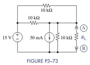
Chapter 3, Problem 3.73P
Find the Thévenin equivalent seen by RL in Figure P3-73.
Expert Solution & Answer
Want to see the full answer?
Check out a sample textbook solution
Students have asked these similar questions
The joint density function of two continuous random variables X and
Y is:
p(x, y) = {cxy
0 < x < 4,1 < y < 5
0
otherwise
Find (i) the constant c
(ii)P(1
Below is a rough schematic of the lighting system for a streetcar powered by a 120 VDC supply. How can I arrange the wires inside the trolley for the interior lights (1-16), headlights (19-20), doors (21-24), and platform lights (17-18), ensuring that each has its own switch?
Does the electrical system require additional safety components? What type of cable can be used for wiring these lights?
12.8 Obtain the inverse Laplace transform of each of the fol-
lowing functions by first applying the partial-fraction-expansion
method.
(a) Fi(s)
6
=
(s+2)(s+4)
(b) F2(s)
=
(c) F3(s) =
4
(s+1)(s+2)2
3s3 +36s2+131s+144
s(s+4)(s²+6s+9)
2s²+4s-10
(d) F4(s)
=
(s+6)(s+2)²
Chapter 3 Solutions
EBK THE ANALYSIS AND DESIGN OF LINEAR C
Ch. 3 - Formulate node-voltage equations for the circuit...Ch. 3 - (a) Formulate node-voltage equations for the...Ch. 3 - (a) Formulate node-voltage equations for the...Ch. 3 - Formulate node-voltage equations for the circuit...Ch. 3 - (a) Formulate node-voltage equations for the...Ch. 3 - Choose a ground wisely and formulate node-voltage...Ch. 3 - The following are a set of node-voltage equations;...Ch. 3 - Choose a ground wisely and formulate node-voltage...Ch. 3 - Formulate node-voltage equations for the circuit...Ch. 3 - Formulate node-voltage equations for the circuit...
Ch. 3 - (a) Formulate mesh-current equations for the...Ch. 3 - (a) Formulate mesh-current equations for the...Ch. 3 - (a) Formulate mesh-current equations for the...Ch. 3 - Prob. 3.16PCh. 3 - Formulate mesh-current equations for the circuit...Ch. 3 - For the circuit of figure P3-19 solve for iA,iB,...Ch. 3 - Formulate mesh-current equations for the circuit...Ch. 3 - The circuit in Figure P3-21 seems to require two...Ch. 3 - Formulate mesh-current equations for the circuit...Ch. 3 - Use simple engineering intuition to find the input...Ch. 3 - In Figure P3-24 all of the resistors are 1k and...Ch. 3 - Use Figure P3-24 and MATLAB to solve the following...Ch. 3 - Formulate mesh-current equations for the circuit...Ch. 3 - Find vO for the block diagram shown in figure...Ch. 3 - Design a voltage-divider circuit that will realize...Ch. 3 - Design a current-divider circuit that will realize...Ch. 3 - Using a single resistor, design a circuit that...Ch. 3 - Find the proportionality constant K=vO/vS for the...Ch. 3 - Find the proportionality constant K=iO/vS for the...Ch. 3 - Find the proportionality constant K=vO/iS for the...Ch. 3 - Find the proportionality constant K=iO/iS for the...Ch. 3 - Find the proportionality constant K=vO/vS for the...Ch. 3 - Use the unit output method to find K and vO in...Ch. 3 - Use the unit output method to find K and vO in...Ch. 3 - Use the unit output method to find K in Figure...Ch. 3 - Use the superposition principle to find vO in...Ch. 3 - Use the superposition principle to find vO in...Ch. 3 - Use the superposition principle to find vO in...Ch. 3 - (a) Use the superposition principle to find vO in...Ch. 3 - A linear circuit containing two sources drives a...Ch. 3 - A block diagram of a linear circuit is shown in...Ch. 3 - A certain linear circuit has four input voltages...Ch. 3 - When the current source is turned off in the...Ch. 3 - For the circuit in Figure P3—51, find the Thévenin...Ch. 3 - For the circuit in Figure P3—52, find the Thévenin...Ch. 3 - For the circuit of Figure P3—53, find the Thévenin...Ch. 3 - Find the Thévenin or Norton equivalent circuit...Ch. 3 - Find the Thévenin or Norton equivalent circuit...Ch. 3 - Find the Thévenin equivalent circuit seen by RL in...Ch. 3 - Find the Norton equivalent seen by RL in Figure...Ch. 3 - You need to determine the Thévenin equivalent...Ch. 3 - Find the Thévenin equivalent seen by RL in figure...Ch. 3 - The purpose of this problem is to use Thévenin...Ch. 3 - The circuit in Figure P3-62 was solved earlier...Ch. 3 - Assume that Figure P3-63 represents a model of the...Ch. 3 - The iv characteristic of the active circuit...Ch. 3 - You have successfully completed the first course...Ch. 3 - The Thévenin equivalent parameters of a practical...Ch. 3 - Use a sequence of source transformations to find...Ch. 3 - The circuit in Figure P3-68 provides power to a...Ch. 3 - A nonlinear resistor is connected across a...Ch. 3 - Prob. 3.71PCh. 3 - Find the Norton equivalent seen by RL in Figure...Ch. 3 - Find the Thévenin equivalent seen by RL in Figure...Ch. 3 - Find the Thévenin equivalent seen by RL in Figure...Ch. 3 - For the circuit of Figure P3-75, find the value of...Ch. 3 - For the circuit of Figure P3-76, find the value of...Ch. 3 - The resistance R in Figure P3-77 is adjusted until...Ch. 3 - When a 5-k resistor is connected across a...Ch. 3 - Find the value of R in the circuit of Figure P3-79...Ch. 3 - For the circuit of Figure P3-80, find the value of...Ch. 3 - A 1-k load needs 10 mA to operate correctly....Ch. 3 - A practical source delivers 25 mA to a load. The...Ch. 3 - A 10-V source is shown in Figure P3-83 that is...Ch. 3 - (a)Select RL and design an interface circuit for...Ch. 3 - The source in Figure P3-85 has a 100-mA output...Ch. 3 - Figure P3-86 shows an interface circuit connecting...Ch. 3 - Prob. 3.87PCh. 3 - In this problem, you will design two interface...Ch. 3 - Two teams are competing to design the interface...Ch. 3 - The bridge-T attenuation pad shown in FigureP3-90...Ch. 3 - Design two interface circuits in Figure P3-91 so...Ch. 3 - Design the interface circuit in Figure P3-91 so...Ch. 3 - Design the interface circuit in Figure P3-93 so...Ch. 3 - It is claimed that both interface circuits in...Ch. 3 - Audio Speaker Resistance-Matching Network A...Ch. 3 - Interface Circuit Design Using no more than three...Ch. 3 - Battery Design A satellite requires a battery with...Ch. 3 - Design Interface Competition The output of a...Ch. 3 - Prob. 3.106IP
Knowledge Booster


Learn more about
Need a deep-dive on the concept behind this application? Look no further. Learn more about this topic, electrical-engineering and related others by exploring similar questions and additional content below.Similar questions
- 12.4 Determine the Laplace transform of each of the followingfunctions by applying the properties given in the Tables (a) f1(t) = 4te−2t u(t)(b) f2(t) = 10cos(12t +60◦) u(t)*(c) f3(t) = 12e−3(t−4) u(t −4)(d) f4(t) = 30(e−3t +e3t ) u(t)(e) f5(t) = 16e−2t cos4t u(t)(f) f6(t) = 20te−2t sin4t u(t)arrow_forward8. Obtain the inverse Laplace transform of each of the followingfunctions by first applying the partial-fraction-expansionmethod.(a) F1(s) =6(s+2)(s+4)(b) F2(s) =4(s+1)(s+2)2(c) F3(s) =3s3 +36s2 +131s+144s(s+4)(s2 +6s+9)(d) F4(s) =2s2 +4s−10(s+6)(s+2)2arrow_forward12.12 In the circuit of Fig. P12.12(a), is(t) is given by the waveform shown in Fig. P12.12(b). Determine iL (t) for t≥ 0, given that R₁ = R₂ = 2 2 and L = 4 H. is() R₁ R2: (a) Circuit is(t) 8A- 8e-21 elle (b) is(t) Figure P12.12 Circuit and waveform for Problem 12.12. iLarrow_forward
- 12.12 In the circuit of Fig. P12.12(a), is(t) is given by thewaveform shown in Fig. P12.12(b). Determine iL(t) for t ≥ 0,given that R1 = R2 = 2 W and L = 4 H.arrow_forward12.4 Determine the Laplace transform of each of the following functions by applying the properties given in Tables 12-1 and 12-2 on pages 642-643. (a) fi(t)=4tet u(t) (b) f2(t)=10cos (12t+60°) u(t) *(c) f3(t) = 12e−3(t−4) u(t −4) (d) f4(t) = 30(e³ +e³t) u(t) (e) fs(t)=16e2t cos 4t u(t) (f) f6(t)=20te 2 sin 4t u(t)arrow_forwarda) Calculate the values of v and i. + 803 1A Va 82 b) Determine the power dissipated in each resistor. 1A Va (a) + I 50 V 0.2 S (b) + D + 1 Α υ€ 20 Ω 50 V 250 ΩΣ ia (c) (d) Copyright ©2015 Pearson Education, All Rights Reservedarrow_forward
- Exercise 3-12: Find the Thévenin equivalent of the circuit to the left of terminals (a, b) in Fig. E3.12, and then determine the current I. 502 502 0.6 Ω 20 V | + <302 Ω ΣΙΩ b 2025 Ω 15A Figure E3.12arrow_forward2. Consider following feedback system. r(t) e(t) y(t) K G(s) 1 where G(S) = s²+as+b In above, K, a and b are constants. Select the values of K, a and b in a way so that (i) (ii) (iii) the closed loop system is stable, steady-state error of the closed-loop system for step input is 0.2, the closed-loop response has 20% overshoot and 2 seconds as settling time.arrow_forward4. Answer the following questions. Take help from ChatGPT to answer these questions (if you need). But write the answers briefly using your own words with no more than two sentences, and make sure you check whether ChatGPT is giving you the appropriate answers in the context of class. a) What is the advantage of the PI controller over the proportional controller? b) What is the advantage of the PD controller over a proportional controller? c) In the presence of noise, what problem do we face implementing the derivate part of the PID (or PD) controller? To address this, what do we usually use? d) What are the forms of lead compensator and lag compensator? How do these two types of compensators differ?arrow_forward
- 3. Consider the following closed-loop system as shown in the figure. 16 Ge(s) s(s + 4) Suppose Ge(s) is a PID controller with Kp = 1, KD = 2 and K₁ = 3. a) Find the controller transfer function G₁(s). b) Find the open-loop transfer function. c) Find the closed-loop transfer function.arrow_forwardExercise 3-12: Find the Thévenin equivalent of the circuit to the left of terminals (a, b) in Fig. E3.12, and then determine the current I. 502 5 Ω 0.6 Ω a 3Ω ΣΙΩ b 20 V 1 + 2027 15A Figure E3.12arrow_forwardsolve and show workarrow_forward
arrow_back_ios
SEE MORE QUESTIONS
arrow_forward_ios
Recommended textbooks for you
 Introductory Circuit Analysis (13th Edition)Electrical EngineeringISBN:9780133923605Author:Robert L. BoylestadPublisher:PEARSON
 Delmar's Standard Textbook Of ElectricityElectrical EngineeringISBN:9781337900348Author:Stephen L. HermanPublisher:Cengage Learning
 Programmable Logic ControllersElectrical EngineeringISBN:9780073373843Author:Frank D. PetruzellaPublisher:McGraw-Hill Education
 Fundamentals of Electric CircuitsElectrical EngineeringISBN:9780078028229Author:Charles K Alexander, Matthew SadikuPublisher:McGraw-Hill Education
 Electric Circuits. (11th Edition)Electrical EngineeringISBN:9780134746968Author:James W. Nilsson, Susan RiedelPublisher:PEARSON
 Engineering ElectromagneticsElectrical EngineeringISBN:9780078028151Author:Hayt, William H. (william Hart), Jr, BUCK, John A.Publisher:Mcgraw-hill Education,
Introductory Circuit Analysis (13th Edition)
Electrical Engineering
ISBN:9780133923605
Author:Robert L. Boylestad
Publisher:PEARSON
Delmar's Standard Textbook Of Electricity
Electrical Engineering
ISBN:9781337900348
Author:Stephen L. Herman
Publisher:Cengage Learning
Programmable Logic Controllers
Electrical Engineering
ISBN:9780073373843
Author:Frank D. Petruzella
Publisher:McGraw-Hill Education
Fundamentals of Electric Circuits
Electrical Engineering
ISBN:9780078028229
Author:Charles K Alexander, Matthew Sadiku
Publisher:McGraw-Hill Education
Electric Circuits. (11th Edition)
Electrical Engineering
ISBN:9780134746968
Author:James W. Nilsson, Susan Riedel
Publisher:PEARSON
Engineering Electromagnetics
Electrical Engineering
ISBN:9780078028151
Author:Hayt, William H. (william Hart), Jr, BUCK, John A.
Publisher:Mcgraw-hill Education,
Thevenin's Theorem; Author: Neso Academy;https://www.youtube.com/watch?v=veAFVTIpKyM;License: Standard YouTube License, CC-BY