
Applied Fluid Mechanics: Global Edition
7th Edition
ISBN: 9781292019611
Author: Robert Mott
Publisher: Pearson Higher Education
expand_more
expand_more
format_list_bulleted
Concept explainers
Videos
Textbook Question
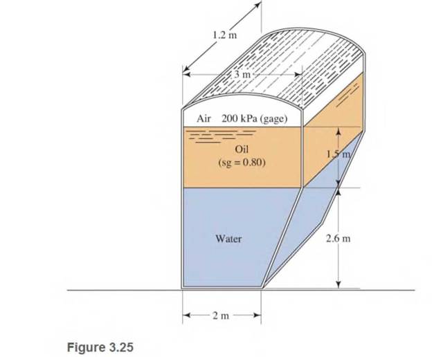
Chapter 3, Problem 3.56PP
Determine the pressure at the bottom of the tank in Fig.3.25
Expert Solution & Answer

Trending nowThis is a popular solution!

Students have asked these similar questions
=
The forces F₁ = 590 lb, F₂ = 380 lb, F3 = 240 lb and F
330 lb. Determine the forces in each member of the truss.
Use positive values to indicate tension and negative values to
indicate compression.
a
a
a
D
b
F₁
A
000
B.
779977
F₂V
H
G
E
F4
b
BY NC SA
2013 Michael Swanbom
Values for dimensions on the figure are given in the following
table. Note the figure may not be to scale.
Variable Value
a
6 ft
b
10.1 ft
The force in member AB is
lb.
The force in member AH is
lb.
The force in member GH is
lb.
The force in member BH is
lb.
The force in member BC is
lb.
The force in member BG is
lb.
The force in member EG is
lb.
The force in member CD is
lb.
The force in member DE is
lb.
The force in member CE is
lb.
The force in member CG is
lb.
Multiple Choice
Circle the best answer to each statement.
1. Which type of surface deviation is controlled by a cy-
lindricity tolerance but not by a circularity tolerance?
A.
B.
C.
Ovality
Taper
Lobing
D. None of the above
2. When verifying a cylindricity tolerance, the inspec-
tion method must be able to collect a set of points and
determine the:
A. Distance between two coaxial cylinders that con-
tain the set of points
B.
Cylinder that circumscribes the set of points
C. Cylinder that inscribes the set of points
D.
Distance between two coaxial circles that contain
the set of points
3. Where Rule #1 applies to a cylindrical regular feature
of size, the tolerance value of a cylindricity tolerance
applied to the feature of size must be
tolerance.
A. Less than
B. Equal to
C. Greater than
D. None of the above
the size
4. Which of the following modifiers may be applied with
a cylindricity tolerance?
A. M
B.
C. ℗
D. Ø
5. Which geometric tolerance can provide an indirect
cylindricity…
The beam AB is attached to the wall in the xz plane by a
fixed support at A. A force of
F = (−129î + 69.0ĵ + 3591) N is applied to the end of
the beam at B. The weight of the beam can be modeled with
a uniform distributed load of intensity w = 85.0 N/m acting in
the negative z direction along its entire length. Find the
support reactions at A.
Z
с
A
b
a
B
F
y
Cc 10
BY NC SA
2016 Eric Davishahl
X
Values for dimensions on the figure are given in the following.
table. Note the figure may not be to scale.
Variable
Value
a
5.60 m
b
5.00 m
C
3.70 m
A
II
=
MA = (
m
2.>
~.>
+
+
k) N
k) N-
Chapter 3 Solutions
Applied Fluid Mechanics: Global Edition
Ch. 3 - Write the expression for computing the pressure in...Ch. 3 - Define absolute pressureCh. 3 - Define gage pressureCh. 3 - Define atmospheric pressureCh. 3 - Write the expression relating gage pressure,...Ch. 3 - State whether statements 3.6-3.10 are (or can be)...Ch. 3 - State whether statements 3.6-3.10 are (or can be)...Ch. 3 - State whether statements 3.6-3.10 are (or can be)...Ch. 3 - State whether statements 3.6-3.10 are (or can be)...Ch. 3 - State whether statements 3.6-3.10 are (or can be)...
Ch. 3 - State whether statements 3.6-3.10 are (or can be)...Ch. 3 - State whether statements 3.6-3.10 are (or can be)...Ch. 3 - State whether statements 3.6-3.10 are (or can be)...Ch. 3 - Problems 3.14-3.33 require that you convert the...Ch. 3 - Problems 3.14-3.33 require that you convert the...Ch. 3 - Problems 3.14-3.33 require that you convert the...Ch. 3 - Problems 3.14-3.33 require that you convert the...Ch. 3 - Problems 3.14-3.33 require that you convert the...Ch. 3 - Problems 3.14-3.33 require that you convert the...Ch. 3 - Problems 3.14-3.33 require that you convert the...Ch. 3 - Problems 3.14-3.33 require that you convert the...Ch. 3 - Problems 3.14-3.33 require that you convert the...Ch. 3 - Problems 3.14-3.33 require that you convert the...Ch. 3 - Problems 3.14-3.33 require that you convert the...Ch. 3 - Problems 3.14-3.33 require that you convert the...Ch. 3 - Problems 3.14-3.33 require that you convert the...Ch. 3 - Problems 3.14-3.33 require that you convert the...Ch. 3 - Problems 3.14-3.33 require that you convert the...Ch. 3 - Problems 3.14-3.33 require that you convert the...Ch. 3 - Problems 3.14-3.33 require that you convert the...Ch. 3 - Problems 3.14-3.33 require that you convert the...Ch. 3 - Problems 3.14-3.33 require that you convert the...Ch. 3 - Problems 3.14-3.33 require that you convert the...Ch. 3 - If milk has a specific gravity of 1.08, what is...Ch. 3 - The pressure in an unknown fluid at a depth of 4.0...Ch. 3 - The pressure at the bottom of a tank of propyl...Ch. 3 - When you dive to a depth of 12.50 ft in seawater,...Ch. 3 - A water storage tank is on the roof of a factory...Ch. 3 - An open tank contains ethylene glycol at 25C....Ch. 3 - For the tank of ethylene glycol described in...Ch. 3 - Figure 3.19 shows a diagram of the hydraulic...Ch. 3 - Figure 3.20 shows a clothes washing machine The...Ch. 3 - An airplane is flying at 10.6km altitude. In its...Ch. 3 - For the tank shown in Fig. 3.21, determine the...Ch. 3 - For the tank shown in Fig. 3.21, determine the...Ch. 3 - For the tank shown in Fig. 3.21. determine the...Ch. 3 - For the tank shown in Fig. 3.21 determine the...Ch. 3 - For the tank in Fig. 3.22, compute the depth of...Ch. 3 - For the tank in Fig. 3.22, compute the depth of...Ch. 3 - Figure 3.22 represents an oil storage drum that is...Ch. 3 - A storage tank for sulfuric acid is 1.5m in...Ch. 3 - A storage drum for crude oil ( sg=0.89 ) is 32 ft...Ch. 3 - The greatest known depth in the ocean is...Ch. 3 - Figure 3.23 shows a closed tank that contains...Ch. 3 - Figure 3.24 shows a closed container holding water...Ch. 3 - Determine the pressure at the bottom of the tank...Ch. 3 - Describe a simple J-tube manometerCh. 3 - Describe a differential U-tube manometer.Ch. 3 - Describe a well-type manometer.Ch. 3 - Describe an inclined well-type manometer.Ch. 3 - Describe a compound manometer.Ch. 3 - Water is in the pipe shown in Fig. 3.26Calculate...Ch. 3 - For the differential manometer shown in Fig. 3.27,...Ch. 3 - For the manometer shown in Fig. 3.28, calculate...Ch. 3 - For the manometer shown in Fig. 3.29, calculate...Ch. 3 - For the manometer shown in Fig. 3.30, calculate...Ch. 3 - For the compound manometer shown in Fig.3.31,...Ch. 3 - For the compound differential manometer in...Ch. 3 - Figure 3.33 shows a manometer being used to...Ch. 3 - For the well-type manometer in Fig. 3.34,...Ch. 3 - Figure 3.35 shows an inclined well-type manometer...Ch. 3 - a. Determine the gage pressure at point A in Fig....Ch. 3 - What is the function of a barometer?Ch. 3 - Describe the construction of a barometer.Ch. 3 - Why is mercury a convenient fluid to use in a...Ch. 3 - If water were to be used instead of mercury in a...Ch. 3 - What is the barometric pressure reading in inches...Ch. 3 - What is the barometric pressure reading in...Ch. 3 - Why must a barometric pressure reading be...Ch. 3 - By how much would the barometric pressure reading...Ch. 3 - Denver, Colorado, is called the "Mile-High City"...Ch. 3 - The barometric pressure is reported to be 28.6 in...Ch. 3 - A barometer indicates the atmospheric pressure to...Ch. 3 - What would be the reading of a barometer in inches...Ch. 3 - Prob. 3.85PPCh. 3 - The pressure in a heating duct is measured to be...Ch. 3 - The pressure in a ventilation duct at the inlet to...Ch. 3 - The pressure in an air conditioning duct is...Ch. 3 - The pressure in a compressed natural gas line is...Ch. 3 - The pressure in a vacuum chamber is 68.2 kPa....Ch. 3 - The pressure in a vacuum chamber is 12.6 psig....Ch. 3 - Prob. 3.92PPCh. 3 - Prob. 3.93PPCh. 3 - A passive solar water heater is to be installed on...Ch. 3 - The elevated tank similar to the one shown in Fig....Ch. 3 - Prob. 3.96PPCh. 3 - A concrete form used to pour a basement wall is to...Ch. 3 - An environmental instrumentation package is to be...Ch. 3 - Prob. 3.99PPCh. 3 - Prob. 3.100PPCh. 3 - A meteorologist reports a "high pressure system"...Ch. 3 - What is the pressure, in psig, at the bottom of a...Ch. 3 - If air has a constant specific weight of...
Additional Engineering Textbook Solutions
Find more solutions based on key concepts
How is the hydrodynamic entry length defined for flow in a pipe? Is the entry length longer in laminar or turbu...
Fluid Mechanics: Fundamentals and Applications
What types of coolant are used in vehicles?
Automotive Technology: Principles, Diagnosis, And Service (6th Edition) (halderman Automotive Series)
CONCEPT QUESTIONS
15.CQ3 The ball rolls without slipping on the fixed surface as shown. What is the direction ...
Vector Mechanics for Engineers: Statics and Dynamics
The solid steel shaft AC has a diameter of 25 mm and is supported by smooth bearings at D and E. It is coupled ...
Mechanics of Materials (10th Edition)
Comprehension Check 7-14
The power absorbed by a resistor can be given by P = I2R, where P is power in units of...
Thinking Like an Engineer: An Active Learning Approach (4th Edition)
How are relationships between tables expressed in a relational database?
Modern Database Management
Knowledge Booster


Learn more about
Need a deep-dive on the concept behind this application? Look no further. Learn more about this topic, mechanical-engineering and related others by exploring similar questions and additional content below.Similar questions
- need help?arrow_forwardA bent pipe is attached to a wall with brackets as shown. A force of F = 180 lb is applied to the end of the tube with direction indicated by the dimensions in the figure. Determine the support reactions at the brackets B, C, and D. Model these brackets as journal bearings (only force reactions perpendicular to the axis of the tube) and neglect couple moment reactions. Assume the distance between the supports at B and C and the tube bends nearby are negligible such that the support at C is directly above the support at D and the dimension g gives the distance between supports B and C. Enter your answers in Cartesian components. 2013 Michael Swanbom cc 10 BY NC SA g h א B 8° У A C x каж Values for dimensions on the figure are given in the table below. Note the figure may not be to scale. Variable Value a 6.72 in b 11.8 in с 14.8 in d 42.0 in h 26.6 in g 28.0 in → The reaction at B is B = lb. The reaction at C is C = lb. The reaction at D is D = lb. + << + + 2. + + 557 〈んarrow_forwardThe force F1 = 10 kN, F2 = 10 kN, F3 = 10 kN, F4 = 5 KN are acting on the sttructure shown. Determine the forces in the members specified below. Use positive values to indicate tension and negative values to indicate compression. F2 D b F1 F3 C E b F4 b B F a G Values for dimensions on the figure are given in the following table. Note the figure may not be to scale. Variable Value a 3 m b 4 m The force in member BC is KN. The force in member BE is KN. The force in member EF is KN.arrow_forward
- h = The transmission tower is subjected to the forces F₁ 3.6 KN at 50° and F2 = 3.3 kN at = 35°. Determine the forces in members BC, BP, PQ, PC, CD, DP and NP. Use positive values to indicate tension and negative values to indicate compression. 不 кажаж в *а*аж E N M d d IF, c B CENTER LINE S อ K F₂ Kbb cc 10 BY NC SA 2013 Michael Swanbom Values for dimensions on the figure are given in the following table. Note the figure may not be to scale. Variable Value a 1.7 m b 4.9 m с 3 m d 5.2 m h 8.4 m Values for dimensions on the figure are given in the following table. Note the figure may not be to scale. Variable Value a 1.7 m 4.9 m с 3 m d 5.2 m h 8.4 m The force in member BC is KN. The force in member BP is KN. The force in member PQ is KN. The force in member PC is KN. The force in member CD is KN. The force in member DP is KN. The force in member NP is KN.arrow_forwardنصاف Sheet Asteel bar of rectangular cross section with dimension Shown in fig. below. This bar is as Connected toawell. Using welded Join a long the sides als only find the weld size (h). Where: Tall = 35 MN/M² F=213.30 answer/h= 4.04 ☐ Yomm Soomm 100mmarrow_forwardFEAarrow_forward
- FEAarrow_forwardHELP?arrow_forwardTrue and False Indicate if each statement is true or false. T/F 1. Rule #1 protects the function of assembly. T/F 2. One of the fundamental dimensioning rules requires all dimensions apply in the free-state condition for rigid parts. T/F 3. The fundamental dimensioning rules that apply on a drawing must be listed in the general notes. T/F 4. Where Rule #1 applies to a drawing, it limits the form of every feature of size on the drawing. T/F 5. Rule #1 limits the variation between features of size on a part. T/F 6. The designer must specify on the drawing which features of size use Rule #1. T/F T/F T/F 7. Rule #1 applies to nonrigid parts (in the unrestrained state). 8. A GO gage is a fixed-limit gage. 9. Rule #1 requires that the form of an individual regular feature of size is controlled by its limits of sizearrow_forward
arrow_back_ios
SEE MORE QUESTIONS
arrow_forward_ios
Recommended textbooks for you
 Elements Of ElectromagneticsMechanical EngineeringISBN:9780190698614Author:Sadiku, Matthew N. O.Publisher:Oxford University Press
 Mechanics of Materials (10th Edition)Mechanical EngineeringISBN:9780134319650Author:Russell C. HibbelerPublisher:PEARSON
 Thermodynamics: An Engineering ApproachMechanical EngineeringISBN:9781259822674Author:Yunus A. Cengel Dr., Michael A. BolesPublisher:McGraw-Hill Education
 Control Systems EngineeringMechanical EngineeringISBN:9781118170519Author:Norman S. NisePublisher:WILEY
 Mechanics of Materials (MindTap Course List)Mechanical EngineeringISBN:9781337093347Author:Barry J. Goodno, James M. GerePublisher:Cengage Learning
 Engineering Mechanics: StaticsMechanical EngineeringISBN:9781118807330Author:James L. Meriam, L. G. Kraige, J. N. BoltonPublisher:WILEY
Elements Of Electromagnetics
Mechanical Engineering
ISBN:9780190698614
Author:Sadiku, Matthew N. O.
Publisher:Oxford University Press
Mechanics of Materials (10th Edition)
Mechanical Engineering
ISBN:9780134319650
Author:Russell C. Hibbeler
Publisher:PEARSON
Thermodynamics: An Engineering Approach
Mechanical Engineering
ISBN:9781259822674
Author:Yunus A. Cengel Dr., Michael A. Boles
Publisher:McGraw-Hill Education
Control Systems Engineering
Mechanical Engineering
ISBN:9781118170519
Author:Norman S. Nise
Publisher:WILEY
Mechanics of Materials (MindTap Course List)
Mechanical Engineering
ISBN:9781337093347
Author:Barry J. Goodno, James M. Gere
Publisher:Cengage Learning
Engineering Mechanics: Statics
Mechanical Engineering
ISBN:9781118807330
Author:James L. Meriam, L. G. Kraige, J. N. Bolton
Publisher:WILEY
Properties of Fluids: The Basics; Author: Swanson Flo;https://www.youtube.com/watch?v=TgD3nEO1iCA;License: Standard YouTube License, CC-BY
Fluid Mechanics-Lecture-1_Introduction & Basic Concepts; Author: OOkul - UPSC & SSC Exams;https://www.youtube.com/watch?v=6bZodDnmE0o;License: Standard Youtube License