
EP ELECTRICAL ENGR.-MODIF.MASTERINGENGR
7th Edition
ISBN: 9780134486994
Author: HAMBLEY
Publisher: PEARSON CO
expand_more
expand_more
format_list_bulleted
Videos
Textbook Question
Chapter 3, Problem 3.51P
A constant voltage of 10V is applied to a
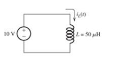
Figure P3 51
The current in the inductance at t = 0 is —100 mA. At what time I, does the current reach +100 mA?
Expert Solution & Answer
Want to see the full answer?
Check out a sample textbook solution
Students have asked these similar questions
Design 5th order LPF with gain = Yo
cut of freq=10KHZ
The current coil of a wattmeter is connected in the red
line of a three-phase system. The voltage circuit can be
connected between the red line and either the yellow
line or the blue line by means of a two-way switch.
Assuming the load to be balanced, show with the aid
of a phasor diagram that the sum of the wattmeter
indications obtained with the voltage circuit connected
to the yellow and the blue lines respectively gives the
total active power.
A wattmeter has its current coil connected in the yellow
line, and its voltage circuit is connected between the
red and blue lines. The line voltage is 400 V and the
balanced load takes a line current of 30 A at a power
factor of 0.7 lagging. Draw circuit and phasor diagrams
and derive an expression for the reading on the wattmeter
in terms of the line voltage and current and of the phase
difference between the phase voltage and current.
Calculate the value of the wattmeter indication.
ANS:
. Line amperes × line volts × sin φ = 8750 var
Chapter 3 Solutions
EP ELECTRICAL ENGR.-MODIF.MASTERINGENGR
Ch. 3 - What is a dielectric material? Give two examples.Ch. 3 - Briefly discuss how current can flow “through” a...Ch. 3 - What current flows through an ideal capacitor if...Ch. 3 - Describe the internal construction of capacitors.Ch. 3 - A voltage of 50 V appears across a 10F capacitor....Ch. 3 - A 2000F capacitor, initially charged to 100V, is...Ch. 3 - A 5F Capacitor ischarged to 1000 V. Determine the...Ch. 3 - The voltage across a 10F capacitor is given by v...Ch. 3 - The voltage across a 1F capacitor is given by...Ch. 3 - Prior to t = 0, a 100F capacitance is uncharged...
Ch. 3 - The current through a 0.5F capacitor is shown in...Ch. 3 - Determine the capacitor voltage, power, and stored...Ch. 3 - A current given by i(t)=Imcos(t) flows through a...Ch. 3 - The current through a 3F capacitor is shown in...Ch. 3 - A constant (dc) current i(t)=3 mA flows into a 50F...Ch. 3 - The energy stored in a 2F capacitor is 200 J and...Ch. 3 - At t=t0 the voltage across a certain capacitance...Ch. 3 - An unusual capacitor has a capacitance that is a...Ch. 3 - For a resistor, what resistance corresponds to a...Ch. 3 - Suppose we have a very large capacitance (ideally,...Ch. 3 - We want to store sufficient energy in a 001-F...Ch. 3 - A 100F capacitor has a voltage given by v(t)=1010...Ch. 3 - How are capacitances combined in series and in...Ch. 3 - Find the equivalent capacitance for each of the...Ch. 3 - Find the equivalent capacitance between terminals...Ch. 3 - A network has a 5F capacitance in series with the...Ch. 3 - What are the minimum and maximum values of...Ch. 3 - Two initially uncharged capacitors C1=15F and...Ch. 3 - Suppose that we are designing a cardiac pacemaker...Ch. 3 - Suppose that we have two 100F capacitors One is...Ch. 3 - Determine the capacitance of a parallel-plate...Ch. 3 - A 100-pF capacitor is constructed of parallel...Ch. 3 - We have a parallel-plate capacitor with plates of...Ch. 3 - Suppose that we have a 1000-pF parallel-plate...Ch. 3 - Two 1F capacitors have an initial voltage of 100 V...Ch. 3 - Prob. 3.36PCh. 3 - Prob. 3.37PCh. 3 - A parallel-plate capacitor is used as a vibration...Ch. 3 - A 0.1F capacitor has a parasitic series resistance...Ch. 3 - Prob. 3.40PCh. 3 - Briefly discuss how inductors are constructed.Ch. 3 - The current flowing through an inductor is...Ch. 3 - If the current through an ideal inductor is...Ch. 3 - Briefly discuss the fluid-flow analogy for an...Ch. 3 - The current flowing through a 2-H inductance is...Ch. 3 - The current flowing through a 100-mH inductance is...Ch. 3 - The current flowing through a 2-H inductance is...Ch. 3 - The voltage across a 2-H inductance is shown in...Ch. 3 - The voltage across a 10 H inductance is given by...Ch. 3 - A 2-H inductance has i(0) = 0 and v(t)=texp(t) for...Ch. 3 - A constant voltage of 10V is applied to a 50H...Ch. 3 - At t = 0, the current flowing in a 05-H inductance...Ch. 3 - The current through a 100-mH inductance is given...Ch. 3 - Prior to t= 0, the current in a 2-H inductance is...Ch. 3 - At t= 0, a constant 5-V voltage source is applied...Ch. 3 - Prob. 3.56PCh. 3 - Al t= 5 s, the energy stored in a 2-H inductor is...Ch. 3 - What value of inductance (having zero initial...Ch. 3 - To what circuit element does a very large...Ch. 3 - The voltage across an inductance L is given by...Ch. 3 - Discuss how inductances are combined in series and...Ch. 3 - Determine the equivalent inductance for each of...Ch. 3 - Find the equivalent inductance for each of the...Ch. 3 - What is the maximum inductance that can be...Ch. 3 - Suppose we want to combine (in series or in...Ch. 3 - Prob. 3.66PCh. 3 - Two inductances L1=1H and L2=2H are connected in...Ch. 3 - A 10-mH inductor has a parasitic series resistance...Ch. 3 - Draw the equivalent circuit for a real inductor,...Ch. 3 - Suppose that the equivalent circuit shown in...Ch. 3 - Consider the circuit shown in Figure P3.71 in...Ch. 3 - The circuit shown in Figure P3.72 has...Ch. 3 - Describe briefly the physical basis for mutual...Ch. 3 - The mutually coupled inductances in Figure P3.74...Ch. 3 - Repeat Problem P3.74 with the dot placed at the...Ch. 3 - a. Derive an expression for the equivalent...Ch. 3 - Consider the parallel inductors shown in Figure...Ch. 3 - Consider the mutually coupled inductors shown in...Ch. 3 - Mutually coupled inductances have...Ch. 3 - The current through a 200-mH inductance is given...Ch. 3 - A 1-H inductance has iL(0)=0 and vL(t)=texp(t) for...Ch. 3 - The current flowing through a 10F capacitor having...Ch. 3 - Determine the equivalent capacitance Ceq for...Ch. 3 - A certain parallel-plate capacitor has plate...Ch. 3 - A 2-mH inductance has iab=0.3sin(2000t)A . Find an...Ch. 3 - Determine the equivalent inductance Leq between...Ch. 3 - Given that vc(t)=10sin(1000t)V , find vs(t)in the...Ch. 3 - Prob. 3.7PTCh. 3 - The current flowing through a 20F capacitor having...
Additional Engineering Textbook Solutions
Find more solutions based on key concepts
Why is the study of database technology important?
Database Concepts (8th Edition)
Locate the centroid of the area. Prob. 9-17
INTERNATIONAL EDITION---Engineering Mechanics: Statics, 14th edition (SI unit)
Computers process data under the control of sets of instructions called
Java How to Program, Early Objects (11th Edition) (Deitel: How to Program)
Assume a telephone signal travels through a cable at two-thirds the speed of light. How long does it take the s...
Electric Circuits. (11th Edition)
What output will the following lines of code display on the screen? cout "The works of Wolfgang\ninclude the f...
Starting Out with C++: Early Objects (9th Edition)
Look at the following description of a problem domain:
Starting Out with Java: From Control Structures through Data Structures (4th Edition) (What's New in Computer Science)
Knowledge Booster


Learn more about
Need a deep-dive on the concept behind this application? Look no further. Learn more about this topic, electrical-engineering and related others by exploring similar questions and additional content below.Similar questions
- 4. The circuit shown below shows an infinite impedance (open circuit) in phase B of the Y-connected load. Find the phasor voltage VOB if the system is 208 V, sequence ABC. -j100 Q 100 Ω B 5. Three identical impedances of Z = 15260°2 are connected in Y to a three-phase, three-wire, 240 V, ABC system. The lines between the supply and the load have impedances of 2 +j 1 Q2. Find the line voltage magnitudes at the load. Find the new values when a set of capacitors with reactance of -j10 Q (Y-connection) is connected in parallel with the load. Draw the vector diagram for the load current, the capacitor current and the system line current.arrow_forward1. A three-phase, three-wire, 240 V, ABC system supplies a delta-connected load in which ZAB = 25/90°, ZBC = 15230° and ZCA = 200°. a) Find the line currents and the total real and reactive powers supplied by the source. Draw the phasor diagram for the line voltages and phase and line currents. Vc VA AT VB ICT 1 CA ZAB | BT ZBC b) A 240 V, 2 HP, 0.95 efficiency, single-phase motor is connected as shown below. The motor is operating at 0.85 p.f. lagging. Repeat (a). Include the motor current in the phasor diagram VA AT ZAB Ꮓ ΑΒ V B CT 1BT M ZBC ZCAarrow_forward2. A three-phase, four-wire, 208 V, ABC system supplies a Y-connected load in which Zд = 100°N, Z = 15/30° and Zc = 104-30°. Find the line currents, the neutral current and total real and reactive powers. Draw the phasor diagram of the phase voltages and currents. ZA = 3. A three-phase, three-wire, 208 V, ABC system supplies a Y-connected load in which ZA 100°, ZB = 15230° and Zc = 10-30°. Find the line currents, the phase voltages across the load impedances, the total real and reactive powers and the voltage Von VA ZAarrow_forward
- Don't use ai to answer I will report you answerarrow_forwardDiscuss the importance of power-factor correction in a.c. systems. A 400 V, 50 Hz, three-phase distribution system supplies a 20 kVA, three-phase induction motor load at a power factor of 0.8 lagging, and a star-connected set of impedances, each having a resistance of 10 Ω and an inductive reactance of 8 Ω. Calculate the capacitance of delta-connected capacitors required to improve the overall power factor to 0.95 lagging. ANS: 75 µF/pharrow_forwardA 3-phase, wye-connected generator induces 2400 V in each of its windings. Calculate the line voltage.arrow_forward
- why Low Pass filter (LPF) R₁C=S V₁ R т Tc Voarrow_forwardDon't use ai to answer I will report you answerarrow_forwardA 60hp,3-phase motor absorbs 50 kW from a 600 V,3-phase line. If the line current is 60 A, calculate the following: a. The efficiency of the motor b. The apparent power absorbed by the motor c. The reactive power absorbed by the motor and the power factor of the motorarrow_forward
- Three 15Ω resistors and three 8Ω reactors are connected as shown in Fig. 18. If the line voltage is 530 V, calculate the following: a. The active, reactive, and apparent power supplied to the 3 -phase load b. The voltage across each resistorarrow_forwardThree resistors are connected in delta. If the line voltage is 13.2kV and the line current is 1202 A, calculate the following: A) the current in and the voltage acroos each resistor B) The power supplied to each resistor and the 3 phase load C) The ohmic value of each resistorarrow_forwardWith the aid of a phasor diagram show that the active power and power factor of a balanced three-phase load can be measured by two wattmeters. For a certain load, one wattmeter indicated 20 kW and the other 5 kW after the voltage circuit of this wattmeter had been reversed. Calculate the active power and the power factor of the load. ANS: 15 kW, 0.327arrow_forward
arrow_back_ios
SEE MORE QUESTIONS
arrow_forward_ios
Recommended textbooks for you
 Delmar's Standard Textbook Of ElectricityElectrical EngineeringISBN:9781337900348Author:Stephen L. HermanPublisher:Cengage Learning
Delmar's Standard Textbook Of Electricity
Electrical Engineering
ISBN:9781337900348
Author:Stephen L. Herman
Publisher:Cengage Learning
Inductors Explained - The basics how inductors work working principle; Author: The Engineering Mindset;https://www.youtube.com/watch?v=KSylo01n5FY;License: Standard Youtube License