
International Edition---engineering Mechanics: Statics, 4th Edition
4th Edition
ISBN: 9781305501607
Author: Andrew Pytel And Jaan Kiusalaas
Publisher: CENGAGE L
expand_more
expand_more
format_list_bulleted
Videos
Textbook Question
Chapter 3, Problem 3.4P
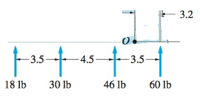
The four forces shown act on the rollers of an in-line skate. Determine the equivalent force-couple system, with the force acting at O (the ankle joint of the skater).
Expert Solution & Answer

Trending nowThis is a popular solution!

Students have asked these similar questions
mylabmastering.pearson.com
Chapter 12 - Lecture Notes.pptx: (MAE 272-01) (SP25) DY...
Document Sharing
P Pearson MyLab and Mastering
User Settings
Part A
P
Course Home
b Success Confirmation of Question Submission | bartleby
A particle moves along an Archimedean spiral
r = (80) ft, where 0 is given in radians. (Figure 1)
If ė = = 4 rad/s and € = 5 rad/s², determine the radial component of the particle's velocity at the instant
Express your answer to three significant figures and include the appropriate units.
Figure
y
r =
Α
?
Vr =
Value
Units
Submit
Request Answer
Part B
Determine the transverse component of the particle's velocity.
Express your answer to three significant figures and include the appropriate units.
о
MÅ
ve =
Value
Submit
Request Answer
Part C
Units
?
1 of 1
Determine the radial component of the particle's acceleration.
Express your answer to three significant figures and include the appropriate units.
Ar =
(80) ft
о
ΜΑ
Value
Units
?
= π/2 rad.
Can you help me with a matlab code? I am trying to plot the keplerian orbital elements over time. I would usually find the orbit using cartesian system and then transform into keplerian orbital elements. Is there a way to directly integrate keplerian orbital elements?
mylabmastering.pearson.com
Chapter 12 - Lecture Notes.pptx: (MAE 272-01) (SP25) DY...
P Pearson MyLab and Mastering
Scores
Chapter 3 Solutions
International Edition---engineering Mechanics: Statics, 4th Edition
Ch. 3 - Determine which of the force systems in (b)...Ch. 3 - Replace the force system acting on the beam by an...Ch. 3 - Replace the force system with an equivalent...Ch. 3 - The four forces shown act on the rollers of an...Ch. 3 - Replace the three forces with an equivalent...Ch. 3 - The force system acting on the machine part is...Ch. 3 - The three forces are perpendicular to the...Ch. 3 - Replace the three forces acting on the...Ch. 3 - When the three forces acting on the...Ch. 3 - Represent each of the force systems with a...
Ch. 3 - A worker applies the forces P=8i+10jlb and Q=8ilb...Ch. 3 - When the three forces are replaced by an...Ch. 3 - Replace the two forces and a couple acting on the...Ch. 3 - The shaft-and-pulley assembly ABCD is driven by...Ch. 3 - Replace the force and the couple with an...Ch. 3 - Determine the resultant force R and its line of...Ch. 3 - The 3200-1b weight is supported by two cables....Ch. 3 - The resultant of the three concurrent forces...Ch. 3 - The overhead electric hoist C rides along a track...Ch. 3 - Determine the resultant of the two forces and the...Ch. 3 - Determine the resultant of the force system shown.Ch. 3 - Determine the resultant of the three forces if (a)...Ch. 3 - Determine the resultant of the force system acting...Ch. 3 - Determine the resultant of the forces shown.Ch. 3 - The resultant of the three forces is a force R...Ch. 3 - The resultant of the four belt tensions and the...Ch. 3 - The resultant of the three forces shown is a...Ch. 3 - The resultant of the three forces is the force...Ch. 3 - The bar AB, which is inclined at the angle to the...Ch. 3 - The values of Fz,Mx, and My for three force...Ch. 3 - State whether the resultant of each force system...Ch. 3 - Determine the resultant of the three cable...Ch. 3 - The resultant of the three cable tensions acts...Ch. 3 - The resultant of the three forces acting along the...Ch. 3 - The resultant of the four forces that act on the...Ch. 3 - Determine the resultant R of the three forces...Ch. 3 - Find the resultant of the three forces acting on...Ch. 3 - The resultant of the forces P1,P2, and the couple...Ch. 3 - Find the resultant of the two forces and the...Ch. 3 - Determine the resultant of the force system acting...Ch. 3 - The wrench shown is the resultant of a...Ch. 3 - Determine the resultant of the four forces.Ch. 3 - The force-couple system acting at O is equivalent...Ch. 3 - The force-couple system consists of the force...Ch. 3 - (a) Replace the force system shown by an...Ch. 3 - During a storm, wind exerts a pressure of 110N/m2,...Ch. 3 - Water pressure acting on the vertical wall of the...Ch. 3 - Determine the resultant of the line load acting on...Ch. 3 - Determine the resultant of the line load acting on...Ch. 3 - Determine the resultant of the line loads acting...Ch. 3 - Find the resultant of the distributed load acting...Ch. 3 - Determine the resultant of the uniformly...Ch. 3 - The figure shows the water pressure acting on the...Ch. 3 - The water pressure acting on a masonry dam varies...Ch. 3 - The concrete pier is subjected to soil pressure...Ch. 3 - Find the resultant of the three forces acting on...Ch. 3 - The resultant of the force system shown is a...Ch. 3 - Determine the resultant of the three forces acting...Ch. 3 - The five forces act at end A of the boom....Ch. 3 - Find the resultant of the distributed load acting...Ch. 3 - Determine the resultant of the line loads acting...Ch. 3 - Replace the force system shown with an equivalent...Ch. 3 - The center of gravity of the 30-lb square plate is...Ch. 3 - Determine the resultant of the force system shown.Ch. 3 - Find the x- and y-coordinates of the point where...Ch. 3 - Replace the force system acting on the pipe with...Ch. 3 - Replace the coplanar force system that acts on the...Ch. 3 - Determine the magnitude of the resultant of the...Ch. 3 - Determine the wrench that is equivalent to the...Ch. 3 - The resultant of the three cable tensions acting...
Knowledge Booster


Learn more about
Need a deep-dive on the concept behind this application? Look no further. Learn more about this topic, mechanical-engineering and related others by exploring similar questions and additional content below.Similar questions
- K mylabmastering.pearson.com Chapter 12 - Lecture Notes.pptx: (MAE 272-01) (SP25) DY... P Pearson MyLab and Mastering Mastering Engineering Back to my courses Course Home Scores Course Homearrow_forwardK mylabmastering.pearson.com Chapter 12 - Lecture Notes.pptx: (MAE 272-01) (SP25) DY... P Pearson MyLab and Mastering Mastering Engineering Back to my courses Course Home Scores Course Homearrow_forwardChapter 12 - Lecture Notes.pptx: (MAE 272-01) (SP25) DY... Scoresarrow_forwardIn a single cylinder, four stroke, single acting gas engine, the cylinder diameter is 180 mm and the stroke is 350 mm . When running at 250 rpm , the mean area of the indicator diagram taken off the engine is 355 mm² , length of diagram 75 mm , scale of the indicator spring 90 kN/m sq per mm , and the number of explosions was counted to be 114 per minute. Calculate the indicated power. so i have already asked this question and got a good answer, however on step 4, i dont understand how they reached 18.43 KW. When i do the math provided, i get the answer 7195.566. Where am i going wrong? thanks StepsTo clarify how we determined the Indicated Power, I'll go over each step in detail. Step 1: Comprehending the Provided Information - Cylinder diameter (in meters) = 180 mm = 0.18 m - Stroke length (in meters) = 350 mm = 0.35 m - Engine speed = 250 rpm -Indicator diagram mean area = 355 mm² The diagram's length is 75 mm; its spring scale is 90 kN/m² per mm, or 90,000 N/m² per mm; and…arrow_forwardIn MATLAB, can you help me simulate an orbit under earth J2 perturbation with the Milankovich orbital elements? Also, can you check to see if they fit the Milankovich constraint equaiton?arrow_forward8. All of the members in the Warren truss of Figure 8 are of length 10 ft. Use the method of sections to determine the forces in the members BD,CD,CE. B A C D E F G 2000 lb 3000 lb 5000 lb Figure 8 Harrow_forwardAn acrobat is walking on a tightrope of length L =20.1 m attached to supports A and B at a distance of 20.0 m apart. The combined weight of the acrobat and his balancing pole is 900 N, and the friction between his shoes and the rope is large enough to prevent him from slipping. Neglecting the weight of the rope and any elastic deformation, determine the deflection (y) and the tension in portion AC and BC of the rope for values of x from 0.5 m to 10 m using 0.5 m increments. 1. Determine the maximum deflection (y) in the rope. 2. Plot tension of AC and BC vs. x (on the same plot with x on the x-axis). Turn in the plot and the table of x, TAC, and TBC (clearly label each). A C 20.0 m Barrow_forward5. A 4000 lb block of concrete is attached by light inextensible cables to the truss in Figure 5. Determine the force in each member. State whether each member is in tension or compression. 3 ΘΑ D E cables all dimensions in feet.arrow_forwardA block hangs from the end of bar AB that is 5.80 meters long and connected to the wall in the xz plane. The bar is supported at end A by a ball joint such that it carries only a compressive force along its axis. The bar is supported in equilibrium at end B by cables BD and BC that connect to the xz plane at points C and D respectively with coordinates given in the figure. The z components of the moments exerted on the bar by these two cables sum to 0. The tension in cable BD is measured to be 210 Newtons. Input answers of zero as 0.00 to avoid an invalid answer due to significant figures. Determine the equivalent force and couple system acting at A that models only the forces exerted by both cables BD → and BC on the bar at B. Enter your results for Feq and Meg in Cartesian Components. Z D (c, 0, d) C (a, 0, b). X A f m B y cc 040 BY NC SA 2016 Eric Davishahl Values for dimensions on the figure are given in the following table. Note the figure may not be to scale. Variable Value a…arrow_forwardA bent tube is attached to a wall with brackets as shown. A force of F = 785 lb is applied to the end of the tube with direction indicated by the dimensions in the figure. a.) Determine the moment about point D due to the force F Enter your answer in Cartesian components with units of ft- lbs. b.) Determine the moment about a line (i.e. axis) running from D to C due to the force F. Enter your answer in Cartesian components with units of ft-lbs. 2013 Michael Swanbom x BY NC SA g Z h A с FK kaz Values for dimensions on the figure are given in the table below. Note the figure may not be to scale. Be sure to align your cartesian unit vectors with the coordinate axes shown in the figure. Variable Value α 4.84 in b 13.2 in с 12.5 in d 30.8 in h 18.7 in 22.0 in →> a. MD=( i+ k) ft- lb →> b. MDC = î + k) ft- lbarrow_forwardF1 3 4 5 P F2 F2 Ꮎ e b 200 3 4 5 F1 The electric pole is subject to the forces shown. Force F1 245 N and force F2 = 310 N with an angle 0 = 20.2°. Determine the moment about point P of all forces. Take counterclockwise moments to be positive. = Values for dimensions on the figure are given in the following table. Note the figure may not be to scale. Variable Value a 2.50 m b 11.3 m с 13.0 m The moment about point P is m. N- If the moment about point P sums up to be zero. Determine the distance c while all other values remained the same. m.arrow_forwardF y b C 10 Z Determine the moment about O due to the force F shown, the magnitude of the force F = 76.0 lbs. Note: Pay attention to the axis. Values for dimensions on the figure are given in the following table. Note the figure may not be to scale. Variable Value a 1.90 ft b 2.80 ft с 2.60 ft d 2.30 ft Mo = lb + k) ft-arrow_forwardarrow_back_iosSEE MORE QUESTIONSarrow_forward_ios
Recommended textbooks for you
 International Edition---engineering Mechanics: St...Mechanical EngineeringISBN:9781305501607Author:Andrew Pytel And Jaan KiusalaasPublisher:CENGAGE L
International Edition---engineering Mechanics: St...
Mechanical Engineering
ISBN:9781305501607
Author:Andrew Pytel And Jaan Kiusalaas
Publisher:CENGAGE L
How to balance a see saw using moments example problem; Author: Engineer4Free;https://www.youtube.com/watch?v=d7tX37j-iHU;License: Standard Youtube License