Loose Leaf For Design Of Machinery (mcgraw-hill Series In Mechanical Engineering)
6th Edition
ISBN: 9781260431308
Author: Robert L. Norton
Publisher: McGraw-Hill Education
expand_more
expand_more
format_list_bulleted
Concept explainers
Videos
Textbook Question
Chapter 3, Problem 3.42P
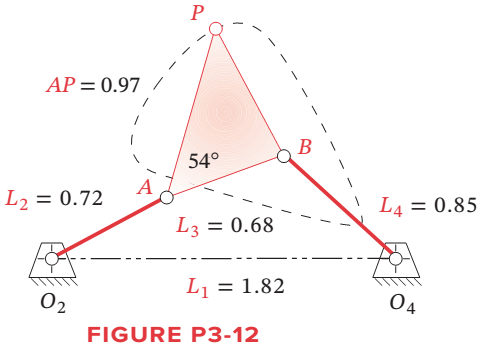
Find the Grashof condition, any limit positions, and the extreme values of the transmission angle (to graphical accuracy) of the linkage in Figure P3-12.
Expert Solution & Answer
Want to see the full answer?
Check out a sample textbook solution
Students have asked these similar questions
1 - Clearly identify the system and its mass and energy exchanges between each system and its surroundings by drawing a box to represent the system boundary, and showing the exchanges by input and output arrows. You may want to search and check the systems on the Internet in case you are not familiar with their operations.
A pot with boiling water on a gas stove
A domestic electric water heater
A motor cycle driven on the roadfrom thermodynamics
You just need to draw and put arrows on the first part a b and c
7. A distributed load
w(x) = 4x1/3
acts on the beam AB shown in Figure 7, where x is measured in meters and w is in kN/m. The
length of the beam is L = 4 m. Find the moment of the resultant force about the point B.
w(x) per unit length
L
Figure 7
B
4. The press in Figure 4 is used to crush a small rock at E. The press comprises three links ABC,
CDE and BG, pinned to each other at B and C, and to the ground at D and G. Sketch free-body
diagrams of each component and hence determine the force exerted on the rock when a vertical
force F = 400 N is applied at A.
210
80
80
C
F
200
B
80
E
60%
-O-D
G
All dimensions in mm.
Figure 4
Chapter 3 Solutions
Loose Leaf For Design Of Machinery (mcgraw-hill Series In Mechanical Engineering)
Ch. 3 - Define the following examples as path, motion, or...Ch. 3 - Design a fourbar Grashof crank-rocker for 90 of...Ch. 3 - Prob. 3.3PCh. 3 - Design a fourbar mechanism to give the two...Ch. 3 - Prob. 3.5PCh. 3 - Prob. 3.6PCh. 3 - Repeat Problem 3-2 with a quick-return time ratio...Ch. 3 - Design a sixbar drag link quick-return linkage for...Ch. 3 - Design a crank-shaper quick-return mechanism for a...Ch. 3 - Find the two cognates of the linkage in Figure...
Ch. 3 - Find the three equivalent geared fivebar linkages...Ch. 3 - Design a sixbar single-dwell linkage for a dwell...Ch. 3 - Design a sixbar double-dwell linkage for a dwell...Ch. 3 - Figure P3-3 shows a treadle-operated grinding...Ch. 3 - Figure P3-4 shows a non-Grashof fourbar linkage...Ch. 3 - Prob. 3.16PCh. 3 - Prob. 3.17PCh. 3 - Prob. 3.18PCh. 3 - Design a pin-jointed linkage that will guide the...Ch. 3 - Figure P3-6 shows a V-link off-loading mechanism...Ch. 3 - Prob. 3.21PCh. 3 - Prob. 3.22PCh. 3 - Figure P3-8 shows a fourbar linkage used in a...Ch. 3 - Prob. 3.24PCh. 3 - Prob. 3.25PCh. 3 - Prob. 3.26PCh. 3 - Prob. 3.27PCh. 3 - Prob. 3.28PCh. 3 - Prob. 3.29PCh. 3 - Prob. 3.30PCh. 3 - Design a Hoeken straight-line linkage to give...Ch. 3 - Design a Hoeken straight-line linkage to give...Ch. 3 - Prob. 3.33PCh. 3 - Prob. 3.34PCh. 3 - Prob. 3.35PCh. 3 - Find the Grashof condition, inversion, any limit...Ch. 3 - Prob. 3.37PCh. 3 - Prob. 3.38PCh. 3 - Prob. 3.39PCh. 3 - Draw the Roberts diagram and find the cognates of...Ch. 3 - Prob. 3.41PCh. 3 - Find the Grashof condition, any limit positions,...Ch. 3 - Prob. 3.43PCh. 3 - Prob. 3.44PCh. 3 - Prob. 3.45PCh. 3 - Prob. 3.46PCh. 3 - Prob. 3.47PCh. 3 - Prob. 3.48PCh. 3 - Prob. 3.49PCh. 3 - Prob. 3.50PCh. 3 - Prob. 3.51PCh. 3 - Prob. 3.52PCh. 3 - Prob. 3.53PCh. 3 - Prob. 3.54PCh. 3 - Prob. 3.55PCh. 3 - Prob. 3.56PCh. 3 - Prob. 3.57PCh. 3 - Prob. 3.58PCh. 3 - Prob. 3.59PCh. 3 - Prob. 3.60PCh. 3 - Prob. 3.61PCh. 3 - Prob. 3.62PCh. 3 - Prob. 3.63PCh. 3 - Prob. 3.64PCh. 3 - Prob. 3.65PCh. 3 - Prob. 3.66PCh. 3 - Design a fourbar Grashof crank-rocker for 120 of...Ch. 3 - Prob. 3.68PCh. 3 - Design a fourbar Grashof crank-rocker for 80 of...Ch. 3 - Design a sixbar drag link quick-return linkage for...Ch. 3 - Design a crank shaper quick-return mechanism for a...Ch. 3 - Design a sixbar, single-dwell linkage for a dwell...Ch. 3 - Design a sixbar, single-dwell linkage for a dwell...Ch. 3 - Prob. 3.74PCh. 3 - Using the method of Example 3-11, show that the...Ch. 3 - Prob. 3.76PCh. 3 - Prob. 3.77PCh. 3 - Prob. 3.78PCh. 3 - The first set of 10 coupler curves on page 1 of...Ch. 3 - Prob. 3.80PCh. 3 - Prob. 3.81PCh. 3 - Prob. 3.82PCh. 3 - Prob. 3.83PCh. 3 - Prob. 3.84PCh. 3 - Prob. 3.85PCh. 3 - Prob. 3.86PCh. 3 - Prob. 3.87PCh. 3 - The side view of the upper section of a...Ch. 3 - Design a fourbar mechanism to give the three...Ch. 3 - Design a fourbar mechanism to give the three...Ch. 3 - Design a fourbar Grashof crank-rocker for 60...Ch. 3 - Design a crank-shaper quick-return mechanism for a...Ch. 3 - Figure P3-22 shows a non-Grashof fourbar linkage...Ch. 3 - Prob. 3.94PCh. 3 - Design a fourbar Grashof crank-rocker for 80...Ch. 3 - Design a sixbar drag link quick-return linkage for...
Knowledge Booster


Learn more about
Need a deep-dive on the concept behind this application? Look no further. Learn more about this topic, mechanical-engineering and related others by exploring similar questions and additional content below.Similar questions
- 2. Figure 2 shows a device for lifting bricks and concrete blocks. It comprises two compo- nents ABC and BD, with a frictionless pin at B. Determine the minimum coefficient of friction required at A and D if the device is to work satisfactorily. W all dimensions in inches Figure 2 Darrow_forward1. The shaft AD in Figure 1 supports two pulleys at B and C of radius 200 mm and 250 mm respectively. The shaft is supported in frictionless bearings at A and D and is rotating clockwise (when viewed from the right) at a constant speed of 300 rpm. Only bearing A can support thrust. The tensions T₁ = 200 N, T₂ = 400 N, and T3 = 300 N. The distances AB = 120 mm, BC = 150 mm, and CD120 mm. Find the tension 74 and the reaction forces at the bearings. A T fo Figure 1arrow_forward5. Figure 5 shows a two-dimensional idealization of the front suspension system for a car. During cornering, the road exerts a vertical force of 5 kN and a leftward horizontal force of 1.2 kN on the tire, which is of 510 mm diameter. Draw free-body diagrams of each component and determine the forces transmitted between them. 250 A -320 B 170 D 170 -220-220- all dimensions in mm. Figure 5arrow_forward
- 8. The force F in Figure 8 is 120 lb and the angle 0 = 25°. Find the axial force N, the shear force V and the bending moment M at the point K which is midway between B and C and illustrate their directions on a sketch of the segment KCD. E -0 B K అ D H 7 A- all dimensions in inches Figure 8 Ꮎ G Farrow_forward6. Determine the coordinates x, y of the centroid of the area shaded in Figure 6. y y=x³ Figure 6 3arrow_forward3. Use the method of sections to determine the forces in the members BD, CD, CE in the struc- ture of Figure 3. A B D 4 kN 6 kN all dimensions in meters. Figure 3arrow_forward
- A pipeline engineer is considering alternative natural gas pipeline routings. The first route is mostly over land and the second is primarily undersea. Both pipelines will need some valve and fitting replacements in year 25. Cost data for each route is shown in Table P2.21. Notice that the undersea route has a higher initial cost due to higher installation costs and extra corrosion protection for the pipeline. However, the undersea route has cheaper security and maintenance costs which substantially reduces annual costs. The MARR for the project is 15%. Determine which route should be pursued based on a present worth analysis.arrow_forwardThe state of stress at a point is σ = -4.00 kpsi, σy Tyz = 8.000 kpsi, and T₂ = -14.00 kpsi. What is the maximum shear stress for this case? The maximum shear stress is kpsi. = 16.00 kpsi, σ = -14.00 kpsi, Try = 11.00 kpsi,arrow_forwardThe initial cost of a proposed heat recovery system is $375,000. The annual operation andmaintenance costs are projected to be $12,000. The salvage value of the system at the end of itsuseful life (projected to be 30 years) is $60,000. The annual savings in fuel costs resulting fromthis system are estimated to be $55,000 per year.a. Assuming annual compounding, determine the rate of return for this heat recovery system.b. If management has set the MARR to be 15% for a heat recovery system like this, what is themaximum initial cost that can be spent on the system (assuming that all other costs and incomesare the same)?arrow_forward
- The initial cost of a machine for a production facility is $225,000. The machine is expected tolast for 10 years with no salvage value. The company’s tax rate is 49% and SLD is used todepreciate the machine. For this type of depreciation, the tax life of the machine is considered 8years and its salvage value is $5,000. The after-tax rate of return is 14.3%. Determine the uniformannual before-tax cash flow.arrow_forwardThree alternatives are being considered for an air cleaning system. All three systems have a lifeof 10 years with no salvage value. System A has an initial cost of $29,000. During the first fiveyears of operation, the annual costs to operate system A are $5,000. During the second five years,the annual cost of system A increases to $16,000. System B has an initial cost of $43,000. Theannual cost to operate system B is $4,000, however, after the first year, this cost increases by$1,600 per year. System C has an initial cost of $58,000 with an annual cost of $2,400. System Crequires two upgrades: one during year 4 which costs $6,000, and the other during year 8 whichcosts $3,000. The MARR for this project is 17%. Determine which air cleaning system should beinstalled based on an economic analysis.arrow_forwardShow all work as much as you can and box out answersarrow_forward
arrow_back_ios
SEE MORE QUESTIONS
arrow_forward_ios
Recommended textbooks for you
 Elements Of ElectromagneticsMechanical EngineeringISBN:9780190698614Author:Sadiku, Matthew N. O.Publisher:Oxford University Press
 Mechanics of Materials (10th Edition)Mechanical EngineeringISBN:9780134319650Author:Russell C. HibbelerPublisher:PEARSON
 Thermodynamics: An Engineering ApproachMechanical EngineeringISBN:9781259822674Author:Yunus A. Cengel Dr., Michael A. BolesPublisher:McGraw-Hill Education
 Control Systems EngineeringMechanical EngineeringISBN:9781118170519Author:Norman S. NisePublisher:WILEY
 Mechanics of Materials (MindTap Course List)Mechanical EngineeringISBN:9781337093347Author:Barry J. Goodno, James M. GerePublisher:Cengage Learning
 Engineering Mechanics: StaticsMechanical EngineeringISBN:9781118807330Author:James L. Meriam, L. G. Kraige, J. N. BoltonPublisher:WILEY
Elements Of Electromagnetics
Mechanical Engineering
ISBN:9780190698614
Author:Sadiku, Matthew N. O.
Publisher:Oxford University Press
Mechanics of Materials (10th Edition)
Mechanical Engineering
ISBN:9780134319650
Author:Russell C. Hibbeler
Publisher:PEARSON
Thermodynamics: An Engineering Approach
Mechanical Engineering
ISBN:9781259822674
Author:Yunus A. Cengel Dr., Michael A. Boles
Publisher:McGraw-Hill Education
Control Systems Engineering
Mechanical Engineering
ISBN:9781118170519
Author:Norman S. Nise
Publisher:WILEY
Mechanics of Materials (MindTap Course List)
Mechanical Engineering
ISBN:9781337093347
Author:Barry J. Goodno, James M. Gere
Publisher:Cengage Learning
Engineering Mechanics: Statics
Mechanical Engineering
ISBN:9781118807330
Author:James L. Meriam, L. G. Kraige, J. N. Bolton
Publisher:WILEY
Power Transmission; Author: Terry Brown Mechanical Engineering;https://www.youtube.com/watch?v=YVm4LNVp1vA;License: Standard Youtube License