
Concept explainers
Videos
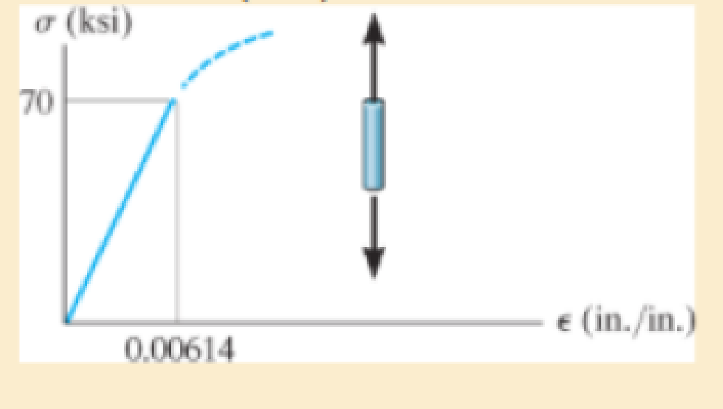
The elastic portion of the tension stress-strain diagram for an aluminum alloy is shown in the figure. The specimen used for the test has a gage length of 2 in. and a diameter of 0.5 in. When the applied load is 9 kip, the new diameter of the specimen is 0.49935 in. Calculate the shear modulus Gal for the aluminum.
The shear modulus for an aluminum alloy
Answer to Problem 3.35RP
The shear modulus for an aluminum alloy is
Explanation of Solution
Given information:
Gage length is
The diameter of the specimen is
The axial load acts on the specimen is
The new diameter of the specimen is
Calculation:
Calculate the modulus of elasticity for aluminum
Here, the stress is
Refer the stress-strain diagram.
The value of stress is 70 ksi and the value of strain is
Substitute 70 ksi for
The expression to find the cross-sectional area of the specimen
Here, the diameter of the specimen is
Substitute
Find the value of stress when the specimen is loaded with a 9 kip load using the relation:
Here, the load is P.
Substitute 9 kip for P and
The expression to find the strain in the longitudinal or axial direction
Here, the Young’s modulus of the aluminum is
Substitute
Find the strain in lateral direction
Here, the new diameter is
Substitute
Find the Poisson’s ratio
Substitute
Calculate the modulus of rigidity for the specimen
Substitute
Therefore, the shear modulus for an aluminum alloy is
Want to see more full solutions like this?
Chapter 3 Solutions
Mechanics of Materials
Additional Engineering Textbook Solutions
Starting Out with Programming Logic and Design (5th Edition) (What's New in Computer Science)
Degarmo's Materials And Processes In Manufacturing
Database Concepts (8th Edition)
Java How to Program, Early Objects (11th Edition) (Deitel: How to Program)
Thinking Like an Engineer: An Active Learning Approach (4th Edition)
Computer Science: An Overview (13th Edition) (What's New in Computer Science)


- The problems are generally based on the following model: A particular spacecraft can be represented as a single axisymmetric rigid body B. Let n₂ be inertially fixed unit vectors; then, 6, are parallel to central, principal axes. To make the mathematics simpler, introduce a frame C where n₂ = ĉ₁ = b; initially. 6₁ Assume a mass distribution such that J =₁₁• B* •b₁ = 450 kg - m² I = b² •Ï¾˜ • b₂ = b¸ •Ï¾* •b¸ = 200 kg - m² K J-I C³ =r₁₁ = r₁₁arrow_forwardThe problems are generally based on the following model: A particular spacecraft can be represented as a single axisymmetric rigid body B. Let n₂ be inertially fixed unit vectors; then, 6, are parallel to central, principal axes. To make the mathematics simpler, introduce a frame C where n₂ = ĉ₁ = b; initially. 6₁ Assume a mass distribution such that J =₁₁• B* •b₁ = 450 kg - m² I = b² •Ï¾˜ • b₂ = b¸ •Ï¾* •b¸ = 200 kg - m² K J-I C³ =r₁₁ = r₁₁arrow_forward##### Determine an example of a design of a compressed air system, which uses the criterion of speed for the design of the pipes (formula attached). The demands of flow rate, power as well as air velocity in the pipelines can be freely chosen. Sizing the compressor (flow, power...) Size reservoir required Setting the dryer Determine the amount of water withdrawn from the system due to air compression **With the attached formula you can choose the appropriate values of the unknownsarrow_forward
- To make an introduction to a report of a simple design of a compressed air system, which uses the criterion of speed, and not that of pressure drop, to determine the diameter of the pipes, where the capacity of the compressor and the demands of the equipment are expressed in flow.arrow_forwardIn an irrigation system, the following characteristics of the pipe network are available.• 100 meters of 4" PVC pipe, 3 gate valves• 500 meters of 3" PVC pipe, 4 gate valves• 200 meters of 2" H.G. pipe, 2 globe valves• 50 litres per second circulate in the pipes:Calculate:1. Total energy losses in meters.2. Leaks in pipes.3. Losses in accessories.4. Calculate the equivalent pipe of that system assuming only pipes without fittings.Solve the problem without artificial intelligence, solve by one of the expertsarrow_forwardLiquid water enters the boiler at 60 bar. Steam exits the boiler at 60 bar, 540°C and undergoes a throttling process to 40 bar before entering the turbine. Steam expands adiabatically through the turbine to 5 bar, 240°C, and then undergoes a throttling process to 1 bar before entering the condenser. Kinetic and potential energy effects can be ignored. Draw a Temperature-Entropy diagram and mark each of the states 2-5 on this diagram. Determine the power generated by the turbine, in kJ per kg of steam flowing. For the valves and the turbine, evaluate the rate of entropy production, each in kJ/K per kg of steam flowing.arrow_forward
- Find the componenets of reactions at pins of A, B and D please show the detailed process and instructions for learning draw out all diagrams please and thank youarrow_forwardA cast iron cylinder of 200 mm inner diameter and 12.5 mm thick is closely wound with a layer of 4 mm diameter steel wire under a tensile stress of 55 MN/m². Determine the stresses set up in the cylinder and steel wire if water under a pressure of 3 MN/m² is admitted in the cylinder. Take E= 100 GN/m², E = 200 GN/m² and Poisson's ratio = 0.25.arrow_forwardWhat is the effect of a clogged fuel injector?arrow_forward
- You are asked to design a unit to condense ammonia. The required condensation rate is 0.09kg/s. Saturated ammonia at 30 o C is passed over a vertical plate (10 cm high and 25 cm wide).The properties of ammonia at the saturation temperature of 30°C are hfg = 1144 ́10^3 J/kg andrho_v = 9.055 kg/m 3 . Use the properties of liquid ammonia at the film temperature of 20°C (Ts =10 o C):Pr = 1.463 rho_l= 610.2 kf/m^3 liquid viscosity= 1.519*10^-4 kg/ ms kinematic viscosity= 2.489*10^-7 m^2/s Cpl= 4745 J/kg C kl=0.4927 W/m C hfg*=hfg+0.68Cpl(Tsat-Given Ts) a) Instead of one plate you want to use small plates and install many of them. Calculate the requiredsurface temperature to achieve the desired condensation rate (0.09 kg/s) if you install 36vertical plates (with the same dimension as above: 10 cm high and 25 cm wide).arrow_forward11-19 designed in Problem The shaft shown in figure P11-4 was 10-19, for the data in the row(s) assigned from table PII-1, and the corresponding diameter of shaft found in Problem 10-19, design suitable bearings 5 E8 cycles at the load for at least State all assumptions. to support 1200rpm. (a) Using hydrodynamically lubricated bronze sleeve bearings with ON = 40, Lld = 0.8, and clearance ratio 0.0025. of a ← gear T gear Key figure PI-4 Given from the problem 10-19 we get d= 1.153 in from the table 11-1 we get a = 16 in b= 18in L= 20inarrow_forwardIn an irrigation system, the following characteristics of the pipe network are available.• 100 meters of 4" PVC pipe, 3 gate valves• 500 meters of 3" PVC pipe, 4 gate valves• 200 meters of 2" H.G. pipe, 2 globe valves• 50 litres per second circulate in the pipes:Calculate:1. Total energy losses in meters.2. Leaks in pipes.3. Losses in accessories.4. Calculate the equivalent pipe of that system assuming only pipes without fittings.Solve the problem without artificial intelligence, solve by one of the expertsarrow_forward
 Mechanics of Materials (MindTap Course List)Mechanical EngineeringISBN:9781337093347Author:Barry J. Goodno, James M. GerePublisher:Cengage Learning