
Videos
Equation of motion of the rod in terms of
Answer to Problem 3.34P
Explanation of Solution
Given:
Wheel radius, R = 0.05m
Mass of rod, m = 20kg
Length of rod, L = 1.4m
Mass of the wheel is negligible and hence the inertia is also negligible.
The wheel does not slip.
Concept used:
The motion of this object is defined by its translational motion in the plane and its rotational motion about an axis perpendicular to the plane. Two force equations describe the translational motion, and a moment equation is needed to describe the rotational motion.
For an objects’ planar motion which rotates only about an axis perpendicular to the plane, the equation of motion can be written down using Newton’s Second Law.
Equation of Motion:
Where
Using Newton’s laws for plane motion,
Where,
Derivation of Equation of motion:
Free body diagram of the rod:
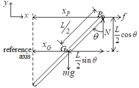
N is the reaction force on the rod.
G is the mass center of the rod.
The displacement from the mass center in the x -direction is measured with respect to the reference axis,
The displacement from the mass center in the y -direction is measured with respect to the horizontal axis through point, P,
The distance between the reference axis and the point P is known.
Equations describing the translational motion:
In the x -direction,
The acceleration for the translational motion is
From the free body diagram, an expression is found for
Differentiate equation
Substitute equation
Substitute the given values, m = 20kg and L = 1.4m in equation
In the y -direction,
The acceleration for the translational motion is
From the free body diagram, an expression is found for
From point, P, there is no vertical displacement.
Differentiate equation
Using the sum of moments find an expression for the reaction force, R.
Mass inertia about the center, G, in the y -direction found using the mass inertia of a hollow cylinder in the y -direction.
Substitute this in the sum of moments equation to find an expression for R.
Substitute equations
Substitute the given values, m = 20kg and L = 1.4m in equation
Conclusion:
Equations of motion of the rod in terms of
Want to see more full solutions like this?
Chapter 3 Solutions
EBK SYSTEM DYNAMICS


- Using AutoCADarrow_forward340 lb 340 lb Δarrow_forward4. In a table of vector differential operators, look up the expressions for V x V in a cylindrical coordinate system. (a) Compute the vorticity for the flow in a round tube where the velocity profile is = vo [1-(³] V₂ = Vo (b) Compute the vorticity for an ideal vortex where the velocity is Ve= r where constant. 2πг (c) Compute the vorticity in the vortex flow given by Ve= r 2лг 1- exp ( r² 4vt (d) Sketch all the velocity and vorticity profiles.arrow_forward
- In the figure, Neglects the heat loss and kinetic and potential energy changes, calculate the work produced by the turbine in kJ T = ??? Steam at P=3 MPa, T = 280°C Turbine Rigid tank V = 1000 m³ Turbine Rigid tank V = 100 m³ V = 1000 m³ V = 100 m³ The valve is opened. Initially: evacuated (empty) tank O a. 802.8 Initially: Closed valve O b. 572 O c. 159.93 Od. 415 e. 627.76 equilibriumarrow_forwardPlease find the torsional yield strength, the yield strength, the spring index, and the mean diameter. Use: E = 28.6 Mpsi, G = 11.5 Mpsi, A = 140 kpsi·in, m = 0.190, and relative cost= 1.arrow_forwardA viscoelastic column is made of a material with a creep compliance of D(t)= 0.75+0.5log10t+0.18(log10t)^2 GPA^-1 for t in s. If a constant compressive stress of σ0 = –100 MPa is applied at t = 0, how long will it take (= t1/2) for the height of the column to decrease to ½ its original value? Note: You will obtain multiple answers for this problem! One makes sense physically and one does not.arrow_forward
- A group of 23 power transistors, dissipating 2 W each, are to be cooled by attaching them to a black-anodized square aluminum plate and mounting the plate on the wall of a room at 30°C. The emissivity of the transistor and the plate surfaces is 0.9. Assuming the heat transfer from the back side of the plate to be negligible and the temperature of the surrounding surfaces to be the same as the air temperature of the room, determine the length of the square plate if the average surface temperature of the plate is not to exceed 50°C. Start the iteration process with an initial guess of the size of the plate as 43 cm. The properties of air at 1 atm and the film temperature of (Ts + T)/2 = (50 + 30)/2 = 40°C are k = 0.02662 W/m·°C, ν = 1.702 × 10⁻⁵ m2 /s, Pr = 0.7255, and β = 0.003195 K–1. Multiple Choice 0.473 m 0.284 m 0.513 m 0.671 marrow_forwardA 40-cm-diameter, 127-cm-high cylindrical hot water tank is located in the bathroom of a house maintained at 20°C. The surface temperature of the tank is measured to be 44°C and its emissivity is 0.4. Taking the surrounding surface temperature to be also 20°C, determine the rate of heat loss from all surfaces of the tank by natural convection and radiation. The properties of air at 32°C are k=0.02603 W/m-K, v=1.627 x 10⁻⁵ m²/s, Pr = 0.7276, and ẞ = 0.003279 K-1 The rate of heat loss from all surfaces of the tank by natural convection is The rate of heat loss from all surfaces of the tank by radiation is W. W.arrow_forwardA 2.5-m-long thin vertical plate is subjected to uniform heat flux on one side, while the other side is exposed to cool air at 5°C. The plate surface has an emissivity of 0.73, and its midpoint temperature is 55°C. Determine the heat flux subjected on the plate surface. Uniform heat flux -Plate, € = 0.73 Cool air 5°C 7 TSUIT Given: The properties of water at Tf,c= 30°C. k=0.02588 W/m.K, v=1.608 x 10⁻⁵ m²/s Pr = 0.7282 The heat flux subjected on the plate surface is W/m²arrow_forward
- Hot water is flowing at an average velocity of 5.82 ft/s through a cast iron pipe (k=30 Btu/h-ft-°F) whose inner and outer diameters are 1.0 in and 1.2 in, respectively. The pipe passes through a 50-ft-long section of a basement whose temperature is 60°F. The emissivity of the outer surface of the pipe is 0.5, and the walls of the basement are also at about 60°F. If the inlet temperature of the water is 150°F and the heat transfer coefficient on the inner surface of the pipe is 30 Btu/h-ft².°F, determine the temperature drop of water as it passes through the basement. Evaluate air properties at a film temperature of 105°C and 1 atm pressure. The properties of air at 1 atm and the film temperature of (Ts+ T∞)/2 = (150+60)/2 = 105°F are k=0.01541 Btu/h-ft-°F. v=0.1838 × 10⁻³ ft2/s, Pr = 0.7253, and ẞ = 0.00177R-1arrow_forwardhand-written solutions only, please. correct answers upvoted!arrow_forwardhand-written solutions only, please. correct answers upvoted!arrow_forward
 Elements Of ElectromagneticsMechanical EngineeringISBN:9780190698614Author:Sadiku, Matthew N. O.Publisher:Oxford University Press
 Mechanics of Materials (10th Edition)Mechanical EngineeringISBN:9780134319650Author:Russell C. HibbelerPublisher:PEARSON
 Thermodynamics: An Engineering ApproachMechanical EngineeringISBN:9781259822674Author:Yunus A. Cengel Dr., Michael A. BolesPublisher:McGraw-Hill Education
 Control Systems EngineeringMechanical EngineeringISBN:9781118170519Author:Norman S. NisePublisher:WILEY
 Mechanics of Materials (MindTap Course List)Mechanical EngineeringISBN:9781337093347Author:Barry J. Goodno, James M. GerePublisher:Cengage Learning
 Engineering Mechanics: StaticsMechanical EngineeringISBN:9781118807330Author:James L. Meriam, L. G. Kraige, J. N. BoltonPublisher:WILEY