
Electrical Engineering: Principles & Applications, Student Value Edition Plus Mastering Engineering with Pearson eText -- Access Card Package (7th Edition)
7th Edition
ISBN: 9780134702193
Author: Allan R. Hambley
Publisher: PEARSON
expand_more
expand_more
format_list_bulleted
Videos
Textbook Question
Chapter 3, Problem 3.24P
Find the equivalent capacitance for each of the circuits shown in Figure P3.24.
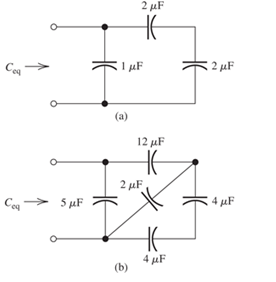
Figure P3.24
Expert Solution & Answer

Trending nowThis is a popular solution!

Learn your wayIncludes step-by-step video

schedule06:13
Students have asked these similar questions
3. Consider the circuit, in which R₁ = 10 KQ2, R2 =
5 KQ, R3 = 1 KQ, and RE = 8 KQ. The supply
voltages are +Vcc = 10 V and -VEE = -5 V. Other
parameters are ẞF = 100, VBE(On) = 0.7 V, and
VCE(Sat) 0.2 V. Rc value will be specified later.
(a) (3 points) Draw the dc equivalent circuit of the
circuit.
VI
+Vcc
Rc
R2
RI
R₁
RE
-VEE
υο
R3
(b) Find the Thevenin equivalent voltage source VEQ and input resistance REQ of the DC
equivalent circuit. Show your work.
+Vcc
Rc
UC
VEQ
www
REQ
VE
VEQ =
REQ =
ΚΩ
RE
VEE
5. Consider the ac equivalent circuit of an
amplifier, where RE = 1 KS2, gm = 0.05 S, and
Υπ= 2Κ Ω.
(a) Redraw the ac equivalent circuit using the
hybrid-pi small signal model for BJTS.
Include ro in the model.
R₁
ww
Vi
RB
ww
+
RL
Vo
RE
(b) Find the terminal resistance RIB using the circuit obtained in (a). Ignore ro. Show your
work. (Don't use formula for RiB.)
4. Consider the circuit. Use the symbol ||
to indicate the parallel of resistors in the
following questions.
(a) Express the input resistance Rin in terms of
the terminal resistance and other necessary
resistor values. (In other words, RiB, Ric, and
RIE are given.)
C₁
R₁
R₂
+Vcc
Rc
C3
R3
C2
ی
RE
-VEE
(b) Express the output resistance Rout in terms of the terminal resistance and other necessary
resistor values. (In other words, RiB, Ric and RiE are given.)
(c) Express the voltage gain A₁ = ∞ in terms of terminal voltage gain Avt, the terminal
Vi
resistance, and other necessary resistor values. (Avt, RiB, Ric and R₁E are given.)
+51
Chapter 3 Solutions
Electrical Engineering: Principles & Applications, Student Value Edition Plus Mastering Engineering with Pearson eText -- Access Card Package (7th Edition)
Ch. 3 - What is a dielectric material? Give two examples.Ch. 3 - Briefly discuss how current can flow “through” a...Ch. 3 - What current flows through an ideal capacitor if...Ch. 3 - Describe the internal construction of capacitors.Ch. 3 - A voltage of 50 V appears across a 10F capacitor....Ch. 3 - A 2000F capacitor, initially charged to 100V, is...Ch. 3 - A 5F Capacitor ischarged to 1000 V. Determine the...Ch. 3 - The voltage across a 10F capacitor is given by v...Ch. 3 - The voltage across a 1F capacitor is given by...Ch. 3 - Prior to t = 0, a 100F capacitance is uncharged...
Ch. 3 - The current through a 0.5F capacitor is shown in...Ch. 3 - Determine the capacitor voltage, power, and stored...Ch. 3 - A current given by i(t)=Imcos(t) flows through a...Ch. 3 - The current through a 3F capacitor is shown in...Ch. 3 - A constant (dc) current i(t)=3 mA flows into a 50F...Ch. 3 - The energy stored in a 2F capacitor is 200 J and...Ch. 3 - At t=t0 the voltage across a certain capacitance...Ch. 3 - An unusual capacitor has a capacitance that is a...Ch. 3 - For a resistor, what resistance corresponds to a...Ch. 3 - Suppose we have a very large capacitance (ideally,...Ch. 3 - We want to store sufficient energy in a 001-F...Ch. 3 - A 100F capacitor has a voltage given by v(t)=1010...Ch. 3 - How are capacitances combined in series and in...Ch. 3 - Find the equivalent capacitance for each of the...Ch. 3 - Find the equivalent capacitance between terminals...Ch. 3 - A network has a 5F capacitance in series with the...Ch. 3 - What are the minimum and maximum values of...Ch. 3 - Two initially uncharged capacitors C1=15F and...Ch. 3 - Suppose that we are designing a cardiac pacemaker...Ch. 3 - Suppose that we have two 100F capacitors One is...Ch. 3 - Determine the capacitance of a parallel-plate...Ch. 3 - A 100-pF capacitor is constructed of parallel...Ch. 3 - We have a parallel-plate capacitor with plates of...Ch. 3 - Suppose that we have a 1000-pF parallel-plate...Ch. 3 - Two 1F capacitors have an initial voltage of 100 V...Ch. 3 - Prob. 3.36PCh. 3 - Prob. 3.37PCh. 3 - A parallel-plate capacitor is used as a vibration...Ch. 3 - A 0.1F capacitor has a parasitic series resistance...Ch. 3 - Prob. 3.40PCh. 3 - Briefly discuss how inductors are constructed.Ch. 3 - The current flowing through an inductor is...Ch. 3 - If the current through an ideal inductor is...Ch. 3 - Briefly discuss the fluid-flow analogy for an...Ch. 3 - The current flowing through a 2-H inductance is...Ch. 3 - The current flowing through a 100-mH inductance is...Ch. 3 - The current flowing through a 2-H inductance is...Ch. 3 - The voltage across a 2-H inductance is shown in...Ch. 3 - The voltage across a 10 H inductance is given by...Ch. 3 - A 2-H inductance has i(0) = 0 and v(t)=texp(t) for...Ch. 3 - A constant voltage of 10V is applied to a 50H...Ch. 3 - At t = 0, the current flowing in a 05-H inductance...Ch. 3 - The current through a 100-mH inductance is given...Ch. 3 - Prior to t= 0, the current in a 2-H inductance is...Ch. 3 - At t= 0, a constant 5-V voltage source is applied...Ch. 3 - Prob. 3.56PCh. 3 - Al t= 5 s, the energy stored in a 2-H inductor is...Ch. 3 - What value of inductance (having zero initial...Ch. 3 - To what circuit element does a very large...Ch. 3 - The voltage across an inductance L is given by...Ch. 3 - Discuss how inductances are combined in series and...Ch. 3 - Determine the equivalent inductance for each of...Ch. 3 - Find the equivalent inductance for each of the...Ch. 3 - What is the maximum inductance that can be...Ch. 3 - Suppose we want to combine (in series or in...Ch. 3 - Prob. 3.66PCh. 3 - Two inductances L1=1H and L2=2H are connected in...Ch. 3 - A 10-mH inductor has a parasitic series resistance...Ch. 3 - Draw the equivalent circuit for a real inductor,...Ch. 3 - Suppose that the equivalent circuit shown in...Ch. 3 - Consider the circuit shown in Figure P3.71 in...Ch. 3 - The circuit shown in Figure P3.72 has...Ch. 3 - Describe briefly the physical basis for mutual...Ch. 3 - The mutually coupled inductances in Figure P3.74...Ch. 3 - Repeat Problem P3.74 with the dot placed at the...Ch. 3 - a. Derive an expression for the equivalent...Ch. 3 - Consider the parallel inductors shown in Figure...Ch. 3 - Consider the mutually coupled inductors shown in...Ch. 3 - Mutually coupled inductances have...Ch. 3 - The current through a 200-mH inductance is given...Ch. 3 - A 1-H inductance has iL(0)=0 and vL(t)=texp(t) for...Ch. 3 - The current flowing through a 10F capacitor having...Ch. 3 - Determine the equivalent capacitance Ceq for...Ch. 3 - A certain parallel-plate capacitor has plate...Ch. 3 - A 2-mH inductance has iab=0.3sin(2000t)A . Find an...Ch. 3 - Determine the equivalent inductance Leq between...Ch. 3 - Given that vc(t)=10sin(1000t)V , find vs(t)in the...Ch. 3 - Prob. 3.7PTCh. 3 - The current flowing through a 20F capacitor having...
Additional Engineering Textbook Solutions
Find more solutions based on key concepts
What are the advantages and disadvantages of implicit declarations?
Concepts Of Programming Languages
What is denormalization?
Database Concepts (8th Edition)
If FB = 700 N, and FC = 560 N, determine the magnitude and coordinate direction angles of the resultant force a...
INTERNATIONAL EDITION---Engineering Mechanics: Statics, 14th edition (SI unit)
Write nested loops to draw this pattern:
Starting Out with Java: From Control Structures through Data Structures (4th Edition) (What's New in Computer Science)
The resistance and inductance of the circuit in Fig. 8.5 are 100 and 20 mH, respectively.
Find the value of C t...
Electric Circuits. (11th Edition)
A loading causes the block to deform into the dashed shape. Explain how to determine the strains AB AC, BC, (A)...
Mechanics of Materials (10th Edition)
Knowledge Booster


Learn more about
Need a deep-dive on the concept behind this application? Look no further. Learn more about this topic, electrical-engineering and related others by exploring similar questions and additional content below.Similar questions
- 2. ẞ 100, VBE(on)= 0.7 V, and VCE(sat) = 0.2 V for the BJT. We want to find the Q-point through the following steps. Show your work. a) Find the bias voltage VTH Using Thevenin's equivalent circuit. R1|| R2 www +5 V R₁ = 20 k IB VTH Answer: VTH = V b) Find the base current voltage IB. www. Answer: IB = μA (note the unit.) c) Find the collector voltage Vc (with reference to the ground). RC= 2.3 k B E R₂ = 30 k -5 V www R₁ = 5 ΚΩ ww AHI› RE= 5 ΚΩarrow_forward3. Consider the circuit, in which R₁ = 10 KQ2, R2 = 5 KQ, R3 = 1 KQ, and RE = 8 KQ. The supply voltages are +Vcc = 10 V and -VEE = -5 V. Other parameters are ẞF = 100, VBE(On) = 0.7 V, and VCE(Sat) 0.2 V. Rc value will be specified later. (a) (3 points) Draw the dc equivalent circuit of the circuit. VI +Vcc Rc R2 RI R₁ RE -VEE υο R3 (b) Find the Thevenin equivalent voltage source VEQ and input resistance REQ of the DC equivalent circuit. Show your work. +Vcc Rc UC VEQ www REQ VE VEQ = REQ = ΚΩ RE VEEarrow_forwardThe solution is with a pen and paper. Really not smartarrow_forward
- 1. Consider the following mechanical system. Obtain the differential equation model for the system. Write the transfer function of the system also. Note here, input u(t) is force and output x(t) is the displacement of the mass. x (Output) k1 k2 www u(t) m (Input force) No frictionarrow_forwardNO AI PLEASEarrow_forward2. Consider the following mechanical system with two masses. Find the differential equation model for the system. Find the transfer functions X1(s) and U(s) Note, in the figure, x₁ and x2 are displacements and u is the force. X2(s) U(s) also. k₁ www + b₁ " x1 k2 kz www mi www m2 Đ b₂arrow_forward
- 4. Find the transfer function H(s) = = Vo(s) V₁(s) for the following circuit. Vi R₁ ww A R₂ ww Voarrow_forwardAnswer the following questions. Take help from ChatGPT to answer these questions (if you need). But write the answers briefly using your own words with no more than two sentences and make sure you check whether ChatGPT is giving you the appropriate answers in our context. A) Write Newton’s second law of motion. B) What is a dashpot? C) What is Hooke’s law? Why there is a negative sign? D) Write the voltage and current equation for an Ideal Op-amp.arrow_forward3. Find the differential Equation model for the following electrical circuit. Write the transfer function also. Here, input u(t) is a current source and output y(t) is the current through the resistor R. u(t) (I) 州 BRarrow_forward
arrow_back_ios
SEE MORE QUESTIONS
arrow_forward_ios
Recommended textbooks for you
 Introductory Circuit Analysis (13th Edition)Electrical EngineeringISBN:9780133923605Author:Robert L. BoylestadPublisher:PEARSON
 Delmar's Standard Textbook Of ElectricityElectrical EngineeringISBN:9781337900348Author:Stephen L. HermanPublisher:Cengage Learning
 Programmable Logic ControllersElectrical EngineeringISBN:9780073373843Author:Frank D. PetruzellaPublisher:McGraw-Hill Education
 Fundamentals of Electric CircuitsElectrical EngineeringISBN:9780078028229Author:Charles K Alexander, Matthew SadikuPublisher:McGraw-Hill Education
 Electric Circuits. (11th Edition)Electrical EngineeringISBN:9780134746968Author:James W. Nilsson, Susan RiedelPublisher:PEARSON
 Engineering ElectromagneticsElectrical EngineeringISBN:9780078028151Author:Hayt, William H. (william Hart), Jr, BUCK, John A.Publisher:Mcgraw-hill Education,
Introductory Circuit Analysis (13th Edition)
Electrical Engineering
ISBN:9780133923605
Author:Robert L. Boylestad
Publisher:PEARSON
Delmar's Standard Textbook Of Electricity
Electrical Engineering
ISBN:9781337900348
Author:Stephen L. Herman
Publisher:Cengage Learning
Programmable Logic Controllers
Electrical Engineering
ISBN:9780073373843
Author:Frank D. Petruzella
Publisher:McGraw-Hill Education
Fundamentals of Electric Circuits
Electrical Engineering
ISBN:9780078028229
Author:Charles K Alexander, Matthew Sadiku
Publisher:McGraw-Hill Education
Electric Circuits. (11th Edition)
Electrical Engineering
ISBN:9780134746968
Author:James W. Nilsson, Susan Riedel
Publisher:PEARSON
Engineering Electromagnetics
Electrical Engineering
ISBN:9780078028151
Author:Hayt, William H. (william Hart), Jr, BUCK, John A.
Publisher:Mcgraw-hill Education,
02 - Sinusoidal AC Voltage Sources in Circuits, Part 1; Author: Math and Science;https://www.youtube.com/watch?v=8zMiIHVMfaw;License: Standard Youtube License