EBK SYSTEM DYNAMICS
3rd Edition
ISBN: 8220100254963
Author: Palm
Publisher: MCG
expand_more
expand_more
format_list_bulleted
Concept explainers
Videos
Textbook Question
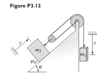
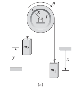
Chapter 3, Problem 3.12P
Instead of using the system shown in Figure 3.2.6a to raise the mass
- Suppose that the friction between the plane and the mass
Expert Solution & Answer
Want to see the full answer?
Check out a sample textbook solution
Students have asked these similar questions
Can you provide steps and an explaination on how the height value to calculate the Pressure at point B is (-5-3.5) and the solution is 86.4kPa.
PROBLEM 3.46
The solid cylindrical rod BC of length L = 600
mm is attached to the rigid lever AB of length a
= 380 mm and to the support at C. When a 500
N force P is applied at A, design specifications
require that the displacement of A not exceed
25 mm when a 500 N force P is applied at A
For the material indicated determine the
required diameter of the rod.
Aluminium: Tall = 65 MPa, G = 27 GPa.
A
Find the equivalent mass of the rocker arm assembly with respect to the x coordinate.
k₁
mi
m2
k₁
Chapter 3 Solutions
EBK SYSTEM DYNAMICS
Ch. 3 - Prob. 3.1PCh. 3 - A baseball is thrown horizontally from the...Ch. 3 - For the mass shown in Figure 3.1.3b. m=10 kg, =25...Ch. 3 - A particle of mass m=19 kg slides down a...Ch. 3 - A particle of mass m slides down a frictionless...Ch. 3 - A radar tracks the flight of a projectile (see...Ch. 3 - Table 3.2.1 gives the inertia IO for a point mass...Ch. 3 - A motor supplies a moment M to the pulley of...Ch. 3 - Figure P3.9 shows an inverted pendulum. Obtain the...Ch. 3 - The two masses shown in Figure P3.10 are released...
Ch. 3 - The motor in Figure P3.11 lifts the mass mL by...Ch. 3 - Instead of using the system shown in Figure 3.2.6a...Ch. 3 - Consider the cart shown in Figure P3.13. Suppose...Ch. 3 - Consider the cart shown in Figure P3.13. Suppose...Ch. 3 - Consider the spur gears shown in Figure P3.15,...Ch. 3 - Consider the spur gears shown in Figure P3.15,...Ch. 3 - Derive the expression for the equivalent inertia...Ch. 3 - Prob. 3.18PCh. 3 - The geared system shown in Figure P3.19 represents...Ch. 3 - Prob. 3.20PCh. 3 - Prob. 3.21PCh. 3 - Prob. 3.22PCh. 3 - For the geared system shown in Figure P3.23,...Ch. 3 - For the geared system discussed in Problem 3.23,...Ch. 3 - The geared system shown in Figure P3.25 is similar...Ch. 3 - Consider the rack-and-pinion gear shown in Figure...Ch. 3 - The lead screw (also called a power screw or a...Ch. 3 - Prob. 3.29PCh. 3 - Derive the equation of motion of the block of mass...Ch. 3 - Assume the cylinder in Figure P3.31 rolls without...Ch. 3 - Prob. 3.33PCh. 3 - Prob. 3.34PCh. 3 - A slender rod 1.4 m long and of mass 20 kg is...Ch. 3 - Prob. 3.36PCh. 3 - Prob. 3.37PCh. 3 - The pendulum shown in Figure P3.38 consists of a...Ch. 3 - Prob. 3.39PCh. 3 - A single link of a robot arm is shown in Figure...Ch. 3 - 3.41 It is required to determine the maximum...Ch. 3 - Figure P3.42 illustrates a pendulum with a base...Ch. 3 - Figure P3.43 illustrates a pendulum with a base...Ch. 3 - 3.44 The overhead trolley shown in Figure P3.44 is...Ch. 3 - Prob. 3.45PCh. 3 - The “sky crane” shown on the text cover was a...
Knowledge Booster


Learn more about
Need a deep-dive on the concept behind this application? Look no further. Learn more about this topic, mechanical-engineering and related others by exploring similar questions and additional content below.Similar questions
- 2. Figure below shows a U-tube manometer open at both ends and containing a column of liquid mercury of length l and specific weight y. Considering a small displacement x of the manometer meniscus from its equilibrium position (or datum), determine the equivalent spring constant associated with the restoring force. Datum Area, Aarrow_forward1. The consequences of a head-on collision of two automobiles can be studied by considering the impact of the automobile on a barrier, as shown in figure below. Construct a mathematical model (i.e., draw the diagram) by considering the masses of the automobile body, engine, transmission, and suspension and the elasticity of the bumpers, radiator, sheet metal body, driveline, and engine mounts.arrow_forward3.) 15.40 – Collar B moves up at constant velocity vB = 1.5 m/s. Rod AB has length = 1.2 m. The incline is at angle = 25°. Compute an expression for the angular velocity of rod AB, ė and the velocity of end A of the rod (✓✓) as a function of v₂,1,0,0. Then compute numerical answers for ȧ & y_ with 0 = 50°.arrow_forward
- 2.) 15.12 The assembly shown consists of the straight rod ABC which passes through and is welded to the grectangular plate DEFH. The assembly rotates about the axis AC with a constant angular velocity of 9 rad/s. Knowing that the motion when viewed from C is counterclockwise, determine the velocity and acceleration of corner F.arrow_forward500 Q3: The attachment shown in Fig.3 is made of 1040 HR. The static force is 30 kN. Specify the weldment (give the pattern, electrode number, type of weld, length of weld, and leg size). Fig. 3 All dimension in mm 30 kN 100 (10 Marks)arrow_forward(read image) (answer given)arrow_forward
- A cylinder and a disk are used as pulleys, as shown in the figure. Using the data given in the figure, if a body of mass m = 3 kg is released from rest after falling a height h 1.5 m, find: a) The velocity of the body. b) The angular velocity of the disk. c) The number of revolutions the cylinder has made. T₁ F Rd = 0.2 m md = 2 kg T T₂1 Rc = 0.4 m mc = 5 kg ☐ m = 3 kgarrow_forward(read image) (answer given)arrow_forward11-5. Compute all the dimensional changes for the steel bar when subjected to the loads shown. The proportional limit of the steel is 230 MPa. 265 kN 100 mm 600 kN 25 mm thickness X Z 600 kN 450 mm E=207×103 MPa; μ= 0.25 265 kNarrow_forward
- T₁ F Rd = 0.2 m md = 2 kg T₂ Tz1 Rc = 0.4 m mc = 5 kg m = 3 kgarrow_forward2. Find a basis of solutions by the Frobenius method. Try to identify the series as expansions of known functions. (x + 2)²y" + (x + 2)y' - y = 0 ; Hint: Let: z = x+2arrow_forward1. Find a power series solution in powers of x. y" - y' + x²y = 0arrow_forward
arrow_back_ios
SEE MORE QUESTIONS
arrow_forward_ios
Recommended textbooks for you
 International Edition---engineering Mechanics: St...Mechanical EngineeringISBN:9781305501607Author:Andrew Pytel And Jaan KiusalaasPublisher:CENGAGE L
International Edition---engineering Mechanics: St...
Mechanical Engineering
ISBN:9781305501607
Author:Andrew Pytel And Jaan Kiusalaas
Publisher:CENGAGE L
Engineering Basics - Statics & Forces in Equilibrium; Author: Solid Solutions - Professional Design Solutions;https://www.youtube.com/watch?v=dQBvQ2hJZFg;License: Standard YouTube License, CC-BY