
Concept explainers
Videos
Compute the power absorbed by each element in the circuit of Fig. 3.68 if the mysterious element X is (a) a 13 Ω resistor; (b) a dependent voltage source labeled 4v1, “+” reference on top; (c) a dependent voltage source labeled 4ix, “+” reference on top.
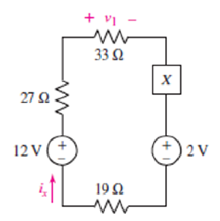
FIGURE 3.68
(a)
Find the power absorbed by each element.
Answer to Problem 28E
Power absorbed by
Explanation of Solution
Given Data:
Element
Formula used:
The expression for power absorbed by voltage source is as follows.
Here,
The expression for power absorbed by resistor is as follows.
Here,
Calculation:
The circuit diagram is redrawn as shown in Figure 1.
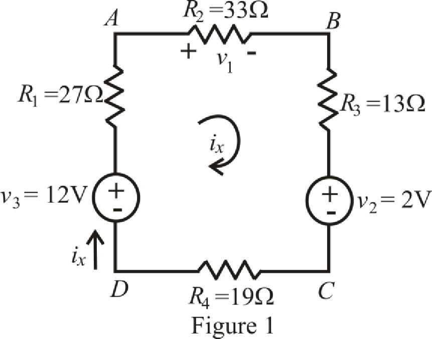
Refer to the redrawn Figure 1.
The expression for KVL in mesh
Here,
Substitute
Rearrange equation (4) for
Current is leaving the positive terminal and we are calculating power absorbed hence current should leave by negative terminal so we will use magnitude of voltage with negative sign, therefore, value of
Substitute
So power absorbed by independent voltage source
Substitute
So, the power absorbed by resistor
Substitute
So power absorbed by resistor
Substitute
So power absorbed by resistor
Substitute
So power absorbed by independent voltage source
Substitute
So power absorbed by resistor
Conclusion:
Thus, power absorbed by
(b)
Find power absorbed by each element.
Answer to Problem 28E
Power absorbed by
Explanation of Solution
Given Data:
Element
Calculation:
The circuit diagram is redrawn as shown in Figure 2,
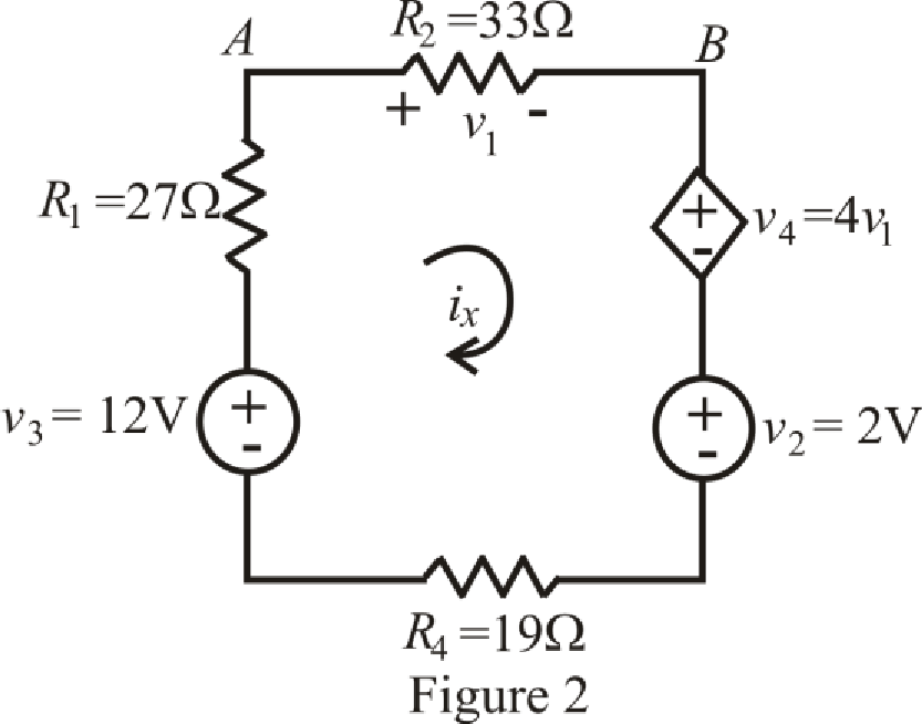
Refer to the redrawn Figure 2,
The expression for KVL in mesh
Here,
The expression for voltage
Here,
The expression for voltage
Here,
Refer to the redrawn Figure 2,
Substitute
Substitute
Rearrange equation (9) for
Current is leaving the positive terminal and we are calculating power absorbed hence current should leave by negative terminal so we will use magnitude of voltage with negative sign, therefore, value of
Substitute
So power absorbed by independent voltage source
Substitute
So power absorbed by resistor
Substitute
So power absorbed by resistor
Substitute
Substitute
Substitute
So power absorbed by dependent voltage source
Substitute
So power absorbed by independent voltage source
Substitute
So power absorbed by resistor
Conclusion:
Thus, power absorbed by
(c)
Find power absorbed by each element.
Answer to Problem 28E
Power absorbed by
Explanation of Solution
Given Data:
Element
Calculation:
The circuit diagram is redrawn as shown in Figure 3.
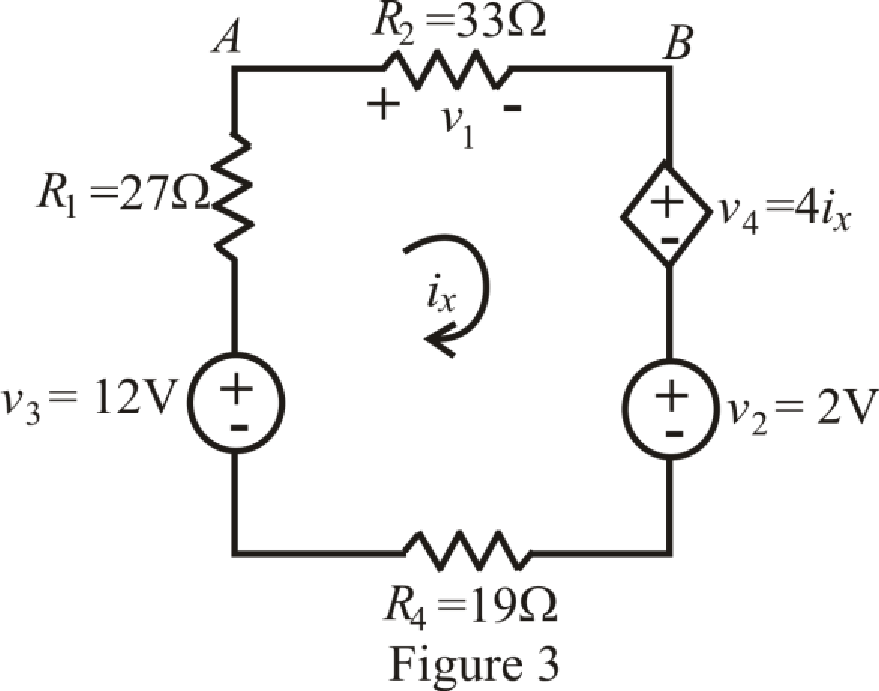
Refer to the redrawn Figure 3,
The expression for KVL in mesh
Here,
The expression for voltage
Here,
Refer to the redrawn Figure 2,
Substitute
Rearrange equation (12) for
Current is leaving the positive terminal and we are calculating power absorbed hence current should leave by negative terminal so we will use magnitude of voltage with negative sign, therefore, value of
Substitute
So power absorbed by independent voltage source
Substitute
So power absorbed by resistor
Substitute
So power absorbed by resistor
Substitute
Substitute
So power absorbed by dependent voltage source
Substitute
So power absorbed by independent voltage source
Substitute
So power absorbed by resistor
Conclusion:
Thus, power absorbed by
Want to see more full solutions like this?
Chapter 3 Solutions
ENGINEERING CIRCUIT...(LL)>CUSTOM PKG.<


- Only expert should attemptarrow_forwardFor the circuit shown below, let l₁ = 9, 1₂ = 14, 13= 12, R₁ = 3, R₂ = 8, and R3 = 5. Use nodal equations to determine V1, V2 and I, as follows: • Consider Node 1, obtain a nodal equation in terms of V₁ and V₂ voltages. Simplify your equation to the format 1V1 + b,V₂ = c, then enter the corresponding values of coefficients b₁ and c₁ 1. b₁ =( C₁ = • Now consider Node 2, obtain a second nodal equation in terms of V₁ and V2 voltages. Simplify your equation to the format -1V₁+b2V2=c2 then enter the corresponding values of coefficients b₂ and c₂ 2. (b₂ = value.) ,၄၇ = - 3. Use (1) and (2) to determine V₂ = 4. Determine V₁ 5. Determine | = i 12 V₁ R1 20 www R2 ww I The relative tolerance for this problem is 5%. R3 This is not a decimal or integer www i3arrow_forwardFor the circuit shown, let V1 = 19 V, Vs2 = 76 V, R₁ = 9, R2 = 9, and R3 = 7. Use Nodal analysis to determine the voltage V2 and the current lo, choose the closet values: V2- 4.788 10 = ○ 2.28 11.978 17.761 35.522 23.957 -9.146 8.32 10.173 A O-7.435 O-5.783 10.531 V sl ་ ་ ་ ན ་་་ ་ ་ ་ ་ ་ ་ ་ ་ +1 ww R₁ R₂ ww R3 Io +1 VS2arrow_forward
- NO AI PLEASEarrow_forwardNO AI PLEASEarrow_forwardProblem 4 Consider the following system. In the figure, y(t) denotes the displacement of the mass and u(t) denotes the force applied to the mass. b1 u(t) y(t) + b2 M 0000 0000 K1 K2 a) Find the differential equation model of the system. b) Find the state-space model for the system. Write x, A, B, C and D clearly in your answer.arrow_forward
- Problem 1 (a) Suppose the Laplace transform of a causal signal x₁ (t) is given by S X₁(s) = 52 +2 Using the Laplace transform properties, find the Laplace transform of the following signal x2(t). x2(t) = e2t+1 x₁(t − 1) - tx₁(2t - 1) (b) Suppose an LTI system T whose impulse response is given by h(t) e 2t 1(t) t 1(t) +28(t) What is the transfer function of the system? (c) If the input x2 (t) is applied to the system T, what will be the output Y₂(s)? Note, you just need to provide Laplace transform of the output y₂(t). Simplification is not needed in any part of this question.arrow_forwardShow workarrow_forwardB) A 60-Hz generator is supply ing 60% of P max to an infinite bus through a reactive network. A fault occurs which increases the reactance of the network between the generator internal voltage and the infinite bus by 400%. When the fault is cleared, the maximum power that can be delivered is 80% of the original maximum value. Determine the critical clearing angle for the condition described.arrow_forward
 Introductory Circuit Analysis (13th Edition)Electrical EngineeringISBN:9780133923605Author:Robert L. BoylestadPublisher:PEARSON
 Delmar's Standard Textbook Of ElectricityElectrical EngineeringISBN:9781337900348Author:Stephen L. HermanPublisher:Cengage Learning
 Programmable Logic ControllersElectrical EngineeringISBN:9780073373843Author:Frank D. PetruzellaPublisher:McGraw-Hill Education
 Fundamentals of Electric CircuitsElectrical EngineeringISBN:9780078028229Author:Charles K Alexander, Matthew SadikuPublisher:McGraw-Hill Education
 Electric Circuits. (11th Edition)Electrical EngineeringISBN:9780134746968Author:James W. Nilsson, Susan RiedelPublisher:PEARSON
 Engineering ElectromagneticsElectrical EngineeringISBN:9780078028151Author:Hayt, William H. (william Hart), Jr, BUCK, John A.Publisher:Mcgraw-hill Education,