
Concept explainers
Videos
The location of the sailboat using graphical method and component method of vector addition.
Answer to Problem 10P
The magnitude of the location of the sailboat is
Explanation of Solution
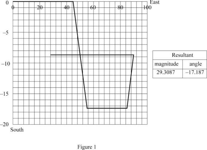
Starting from the origin, each vector is drawn beginning at the end of its preceding vector.
The graphical representation of the path of the sailboat is given below:
Write the expression for y-component of the position of the sailboat
Here,
Write the expression for x-component of the position of the sailboat
Here,
Write the expression for magnitude of the resultant vector
Here,
Write the expression for angle of the resultant vector
Here,
Conclusion:
Substitute
Substitute
Substitute
Substitute
Thus, the magnitude of the location of the sailboat is
Want to see more full solutions like this?
Chapter 3 Solutions
COLLEGE PHYICS


- Refer to the image attachedarrow_forwardShrinking Loop. A circular loop of flexible iron wire has an initial circumference of 161 cm , but its circumference is decreasing at a constant rate of 15.0 cm/s due to a tangential pull on the wire. The loop is in a constant uniform magnetic field of magnitude 1.00 T , which is oriented perpendicular to the plane of the loop. Assume that you are facing the loop and that the magnetic field points into the loop. Find the magnitude of the emf E induced in the loop after exactly time 9.00 s has passed since the circumference of the loop started to decrease. Find the direction of the induced current in the loop as viewed looking along the direction of the magnetic field. Please explain all stepsarrow_forwardMake up an application physics principle problem that provides three (3) significant equations based on the concepts of capacitors and ohm's law.arrow_forward
- A straight horizontal garden hose 38.0 m long with an interior diameter of 1.50 cm is used to deliver 20oC water at the rate of 0.590 liters/s. Assuming that Poiseuille's Law applies, estimate the pressure drop (in Pa) from one end of the hose to the other.arrow_forwardA rectangle measuring 30.0 cm by 40.0 cm is located inside a region of a spatially uniform magnetic field of 1.70 T , with the field perpendicular to the plane of the coil (the figure (Figure 1)). The coil is pulled out at a steady rate of 2.00 cm/s traveling perpendicular to the field lines. The region of the field ends abruptly as shown. Find the emf induced in this coil when it is all inside the field, when it is partly in the field, and when it is fully outside. Please show all steps.arrow_forwardA rectangular circuit is moved at a constant velocity of 3.00 m/s into, through, and then out of a uniform 1.25 T magnetic field, as shown in the figure (Figure 1). The magnetic field region is considerably wider than 50.0 cm . Find the direction (clockwise or counterclockwise) of the current induced in the circuit as it is going into the magnetic field (the first case), totally within the magnetic field but still moving (the second case), and moving out of the field (the third case). Find the magnitude of the current induced in the circuit as it is going into the magnetic field . Find the magnitude of the current induced in the circuit as it is totally within the magnetic field but still moving. Find the magnitude of the current induced in the circuit as it is moving out of the field. Please show all stepsarrow_forward
- Shrinking Loop. A circular loop of flexible iron wire has an initial circumference of 161 cm , but its circumference is decreasing at a constant rate of 15.0 cm/s due to a tangential pull on the wire. The loop is in a constant uniform magnetic field of magnitude 1.00 T , which is oriented perpendicular to the plane of the loop. Assume that you are facing the loop and that the magnetic field points into the loop. Find the magnitude of the emf E induced in the loop after exactly time 9.00 s has passed since the circumference of the loop started to decrease. Find the direction of the induced current in the loop as viewed looking along the direction of the magnetic field. Please explain all stepsarrow_forwardA circular loop of wire with radius 0.0480 m and resistance 0.163 Ω is in a region of spatially uniform magnetic field, as shown in the following figure (Figure 1). The magnetic field is directed out of the plane of the figure. The magnetic field has an initial value of 7.88 T and is decreasing at a rate of -0.696 T/s . Is the induced current in the loop clockwise or counterclockwise? What is the rate at which electrical energy is being dissipated by the resistance of the loop? Please explain all stepsarrow_forwardA 0.333 m long metal bar is pulled to the left by an applied force F and moves to the left at a constant speed of 5.90 m/s. The bar rides on parallel metal rails connected through a 46.7 Ω resistor, as shown in (Figure 1), so the apparatus makes a complete circuit. You can ignore the resistance of the bar and rails. The circuit is in a uniform 0.625 T magnetic field that is directed out of the plane of the figure. Is the induced current in the circuit clockwise or counterclockwise? What is the rate at which the applied force is doing work on the bar? Please explain all stepsarrow_forward
- A 0.850-m-long metal bar is pulled to the right at a steady 5.0 m/s perpendicular to a uniform, 0.650-T magnetic field. The bar rides on parallel metal rails connected through a 25-Ω, resistor (Figure 1), so the apparatus makes a complete circuit. Ignore the resistance of the bar and the rails. Calculate the magnitude of the emf induced in the circuit. Find the direction of the current induced in the circuit. Calculate the current through the resistor.arrow_forwardIn the figure, a conducting rod with length L = 29.0 cm moves in a magnetic field B→ of magnitude 0.510 T directed into the plane of the figure. The rod moves with speed v = 5.00 m/s in the direction shown. When the charges in the rod are in equilibrium, which point, a or b, has an excess of positive charge and where does the electric field point? What is the magnitude E of the electric field within the rod, the potential difference between the ends of the rod, and the magnitude E of the motional emf induced in the rod? Which point has a higher potential? Please explain all stepsarrow_forwardExamine the data and % error values in Data Table 2 where the mass of the pendulum bob increased but the angular displacement and length of the simple pendulum remained constant. Describe whether or not your data shows that the period of the pendulum depends on the mass of the pendulum bob, to within a reasonable percent error.arrow_forward
 College PhysicsPhysicsISBN:9781305952300Author:Raymond A. Serway, Chris VuillePublisher:Cengage Learning
 University Physics (14th Edition)PhysicsISBN:9780133969290Author:Hugh D. Young, Roger A. FreedmanPublisher:PEARSON
 Introduction To Quantum MechanicsPhysicsISBN:9781107189638Author:Griffiths, David J., Schroeter, Darrell F.Publisher:Cambridge University Press
 Physics for Scientists and EngineersPhysicsISBN:9781337553278Author:Raymond A. Serway, John W. JewettPublisher:Cengage Learning
 Lecture- Tutorials for Introductory AstronomyPhysicsISBN:9780321820464Author:Edward E. Prather, Tim P. Slater, Jeff P. Adams, Gina BrissendenPublisher:Addison-Wesley
 College Physics: A Strategic Approach (4th Editio...PhysicsISBN:9780134609034Author:Randall D. Knight (Professor Emeritus), Brian Jones, Stuart FieldPublisher:PEARSON