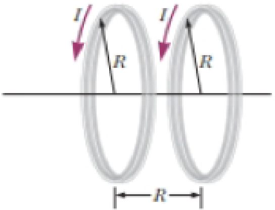
Two circular coils of radius R, each with N turns, are perpendicular to a common axis. The coil centers are a distance R apart. Each coil carries a steady current I in the same direction as shown in Figure P29.38. (a) Show that the magnetic field on the axis at a distance x from the center of one coil is

(a)
To show: The magnetic field on the axis at a distance
Answer to Problem 38AP
Hence, the magnetic field on the axis at a distance
Explanation of Solution
Given information: The radius of each coil is
Let consider a point at
Formula to calculate the magnetic field at a point due to first circular coil is,
Here,
Formula to calculate the magnetic field to the same point due to second circular coil is,
Here,
Write the expression for the net field at the given point.
Substitute
Simplify the above equation for
Conclusion:
Therefore, the magnetic field on the axis at a distance
(b)
To show: The value of
Answer to Problem 38AP
Hence, the value of
Explanation of Solution
Given information: The radius of each coil is
From equation (3), the expression for the net magnetic field is given by,
Differentiate the above equation with respect to
Substitute
Thus, the value of value of
Differentiate the equation (4) with respect to
Substitute
Thus, the value of value of
Conclusion:
Therefore, the value of
Want to see more full solutions like this?
Chapter 29 Solutions
Bundle: Physics For Scientists And Engineers With Modern Physics, 10th + Webassign Printed Access Card For Serway/jewett's Physics For Scientists And Engineers, 10th, Multi-term
Additional Science Textbook Solutions
SEELEY'S ANATOMY+PHYSIOLOGY
Fundamentals of Physics Extended
Chemistry: Atoms First
Brock Biology of Microorganisms (15th Edition)
Human Biology: Concepts and Current Issues (8th Edition)
Human Physiology: An Integrated Approach (8th Edition)
- Lab Assignment #3 Vectors 2. Determine the magnitude and sense of the forces in cables A and B. 30° 30° 300KN 3. Determine the forces in members A and B of the following structure. 30° B 200kN Name: TA: 4. Determine the resultant of the three coplanar forces using vectors. F₁ =500N, F₂-800N, F, 900N, 0,-30°, 62-50° 30° 50° F₁ = 500N = 900N F₂ = 800Narrow_forwardLab Assignment #3 Vectors Name: TA: 1. With the equipment provided in the lab, determine the magnitude of vector A so the system is in static equilibrium. Perform the experiment as per the figure below and compare the calculated values with the numbers from the spring scale that corresponds to vector A. A Case 1: Vector B 40g Vector C 20g 0 = 30° Vector A = ? Case 2: Vector B 50g Vector C = 40g 0 = 53° Vector A ? Case 3: Vector B 50g Vector C 30g 0 = 37° Vector A = ?arrow_forwardThree point-like charges are placed at the corners of an equilateral triangle as shown in the figure. Each side of the triangle has a length of 20.0 cm, and the point (A) is located half way between q1 and q2 along the side. Find the magnitude of the electric field at point (A). Let q1=-1.30 µC, q2=-4.20µC, and q3= +4.30 µC. __________________ N/Carrow_forward
- Find the total capacitance in micro farads of the combination of capacitors shown in the figure below. 2.01 0.30 µF 2.5 µF 10 μF × HFarrow_forwardI do not understand the process to answer the second part of question b. Please help me understand how to get there!arrow_forwardRank the six combinations of electric charges on the basis of the electric force acting on 91. Define forces pointing to the right as positive and forces pointing to the left as negative. Rank in increasing order by placing the most negative on the left and the most positive on the right. To rank items as equivalent, overlap them. ▸ View Available Hint(s) [most negative 91 = +1nC 92 = +1nC 91 = -1nC 93 = +1nC 92- +1nC 93 = +1nC -1nC 92- -1nC 93- -1nC 91= +1nC 92 = +1nC 93=-1nC 91 +1nC 92=-1nC 93=-1nC 91 = +1nC 2 = −1nC 93 = +1nC The correct ranking cannot be determined. Reset Help most positivearrow_forward
 Physics for Scientists and Engineers: Foundations...PhysicsISBN:9781133939146Author:Katz, Debora M.Publisher:Cengage Learning
 Principles of Physics: A Calculus-Based TextPhysicsISBN:9781133104261Author:Raymond A. Serway, John W. JewettPublisher:Cengage Learning
 Physics for Scientists and Engineers, Technology ...PhysicsISBN:9781305116399Author:Raymond A. Serway, John W. JewettPublisher:Cengage Learning
 Physics for Scientists and Engineers with Modern ...PhysicsISBN:9781337553292Author:Raymond A. Serway, John W. JewettPublisher:Cengage Learning
 Physics for Scientists and EngineersPhysicsISBN:9781337553278Author:Raymond A. Serway, John W. JewettPublisher:Cengage Learning


