
Delmar's Standard Textbook of Electricity (MindTap Course List)
6th Edition
ISBN: 9781285852706
Author: Stephen L. Herman
Publisher: Cengage Learning
expand_more
expand_more
format_list_bulleted
Concept explainers
Videos
Textbook Question
Chapter 29, Problem 1RQ
How many transformers are needed to make an open-delta connection?
Expert Solution & Answer
To determine
The number of transformers needed to make an open delta connection.
Answer to Problem 1RQ
Two transformers are needed to make an open delta connection.
Explanation of Solution
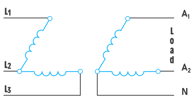
The open delta connection is used when the amount of three-phase power needed is not excessive. From the figure it can be seen that the open-delta transformer connection can be made with only two transformers. The total output power is 86.6% of the sum of the power rating of the two transformers when an open-delta connection is used.
Want to see more full solutions like this?
Subscribe now to access step-by-step solutions to millions of textbook problems written by subject matter experts!
Students have asked these similar questions
Can you rewrite the solution because it is
unclear?
Q2
AM
①(+) = 8 (1+0.5 cos 1000πt +0.5 ros 2000kt)
$4+) = 45
=
*cos 10000 πt.
8 cos wat + 4 cosat + 4 cos Wat coswet.
j1000016
+4e
-j10000πt j11000Rt
j gooort -j 9000 πt
+
e
+e
j sooort
te
+e
J11000 t
+ e
te
j 12000rt.
-J12000 kt
+ с
= 8th S(W- 100007) + 8 IS (W-10000)
<&(w) =
USB
-5-5
-4-5-4
b) Pc 2² = 64
PSB =
42
+ 4
2
Pt Pc+ PSB =
y = Pe
c) Puss =
PLSB =
= 32
4² = 8 w
32+ 8 =
× 100% = 140
(1)³×2×2
31
= 20%
x 2 = 3w
302
USB
4.5 5 5.6 6
ms Ac = 4 mi
= 0.5
mz Ac = 4
५
M2
=
=0.5
A. Draw the waveform for the following binary sequence using Bipolar RZ, Bipolar NRZ, and
Manchester code.
Data sequence= (00110100)
B. In a binary PCM system, the output signal-to-quantization ratio is to be hold to a minimum of
50 dB. If the message is a single tone with fm-5 kHz. Determine:
1) The number of required levels, and the corresponding output signal-to-quantizing noise ratio.
2) Minimum required system bandwidth.
Find Io using Mesh analysis
Chapter 29 Solutions
Delmar's Standard Textbook of Electricity (MindTap Course List)
Ch. 29 - How many transformers are needed to make an...Ch. 29 - Two transformers rated at 100 kVA each are...Ch. 29 - How does the NEC specify that the high leg of a...Ch. 29 - An open-delta three-phase transformer system has...Ch. 29 - If a single-phase load is connected across the two...Ch. 29 - A three-phase transformer connection has a...Ch. 29 - A three-phase transformer connection has a...Ch. 29 - A three-phase transformer bank has the secondary...Ch. 29 - A three-phase transformer bank has the primary and...Ch. 29 - Referring to the transformer connection in...
Knowledge Booster


Learn more about
Need a deep-dive on the concept behind this application? Look no further. Learn more about this topic, electrical-engineering and related others by exploring similar questions and additional content below.Similar questions
- FM station of 100 MHz carrier frequency modulated by a 20 kHz sinusoid with an amplitude of 10 volt, so that the peak frequency deviation is 25 kHz determine: 1) The BW of the FM signal. 2) The approximated BW if the modulating signal amplitude is increased to 50 volt. 3) The approximated BW if the modulating signal frequency is increased by 70%. 4) The amplitude of the modulating signal if the BW is 65 kHz.arrow_forwardAn FDM is used to multiplex two groups of signals using AM-SSB, the first group contains 25 speech signals, each has maximum frequency of 4 kHz, the second group contains 15 music signals, each has maximum frequency of 10 kHz. A guard bandwidth of 500 Hz is used bety each two signals and before the first one. 1. Find the BWmultiplexing 2. Find the BWtransmission if the multiplexing signal is modulated using AM-DSB-LC.arrow_forwardAn FM signal with 75 kHz deviation, has an input signal-to-noise ratio of 18 dB, with a modulating frequency of 15 kHz. 1) Find SNRO at demodulator o/p. 2) Find SNRO at demodulator o/p if AM is used with m=0.3. 3) Compare the performance in case 1) and 2).. Hint: for single tone AM-DSB-LC, SNR₁ = (2m²) (4)arrow_forward
- Find Va and Vb using Nodal analysisarrow_forward4. A battery operated sensor transmits to a receiver that is plugged in to a power outlet. The device is continuously operated. The battery is a 3.6 V coin-cell battery with a 245mAHr capacity. The application requires a bit rate of 36 Mbps and an error rate of less than 10^-3. The channel has a center frequency of 2.4 GHz, a bandwidth of 10 MHz and a noise power spectral density of 10^-14 W/Hz. The maximum distance is 36 meters and the losses in the channel attenuates the signal by 0.25 dB/meter. Your company has two families of chips that you can use. An M-ary ASK and an M-ary QAM chip. The have very different power requirements as shown in the table below. The total current for the system is the current required to achieve the desired Eb/No PLUS the current identified below: Hokies PSK Chip Set Operating Current NOT Including the required Eb/No for the application Hokies QAM Chip Set Operating Current NOT Including the required Eb/No for the application Chip ID M-ary Voltage (volts)…arrow_forwardUsing the 802.11a specifications given below, in Matlab (or similar tool) create the time domain signal for one OFDM symbol using QPSK modulation. See attached plot for the QPSK constellation. Your results should include the power measure in the time and frequency domain and comment on those results. BW 802.11a OFDM PHY Parameters 20 MHZ OBW Subcarrer Spacing Information Rate Modulation Coding Rate Total Subcarriers Data Subcarriers Pilot Subcarriers DC Subcarrier 16.6 MHZ 312.5 Khz (20MHz/64 Pt FFT) 6/9/12/18/24/36/48/54 Mbits/s BPSK, QPSK, 16QAM, 64QAM 1/2, 2/3, 3/4 52 (Freq Index -26 to +26) 48 4 (-21, -7, +7, +21) *Always BPSK Null (0 subcarrier) 52 subarriers -7 (48 Data, 4 Pilot (BPSK), 1 Null) -26 -21 0 7 21 +26 14 One Subcarrier 1 OFDM symbol 1 OFDM Burst -OBW 16.6 MHz BW 20 MHZ 1 constellation point = 52 subcarriers = one or more OFDM symbols 802.11a OFDM Physical Parameters Show signal at this point x bits do Serial Data d₁ S₁ Serial-to- Input Signal Parallel Converter IFFT…arrow_forward
- Find Vb and Va using Mesh analysisarrow_forward1. The communication channel bandwidth is 25 MHz centered at 1GHz and has a noise power spectral density of 10^-9 W/Hz. The channel loss between the transmitter and receiver is 25dB. The application requires a bit rate of 200Mbps and BER of less than 10^-4. Excluding Mary FSK, Determine the minimum transmit power required.arrow_forward2. An existing system uses noncoherent BASK. The application requires a BER of <10^-5. The current transmit power is 25 Watts. If the system changes to a coherent BPSK modulation scheme, what is the new transmit power required to deliver the same BER?arrow_forward
arrow_back_ios
SEE MORE QUESTIONS
arrow_forward_ios
Recommended textbooks for you
 Delmar's Standard Textbook Of ElectricityElectrical EngineeringISBN:9781337900348Author:Stephen L. HermanPublisher:Cengage Learning
 Power System Analysis and Design (MindTap Course ...Electrical EngineeringISBN:9781305632134Author:J. Duncan Glover, Thomas Overbye, Mulukutla S. SarmaPublisher:Cengage Learning
 EBK ELECTRICAL WIRING RESIDENTIALElectrical EngineeringISBN:9781337516549Author:SimmonsPublisher:CENGAGE LEARNING - CONSIGNMENT
Delmar's Standard Textbook Of Electricity
Electrical Engineering
ISBN:9781337900348
Author:Stephen L. Herman
Publisher:Cengage Learning
Power System Analysis and Design (MindTap Course ...
Electrical Engineering
ISBN:9781305632134
Author:J. Duncan Glover, Thomas Overbye, Mulukutla S. Sarma
Publisher:Cengage Learning
EBK ELECTRICAL WIRING RESIDENTIAL
Electrical Engineering
ISBN:9781337516549
Author:Simmons
Publisher:CENGAGE LEARNING - CONSIGNMENT
TRANSFORMERS - What They Are, How They Work, How Electricians Size Them; Author: Electrician U;https://www.youtube.com/watch?v=tXPy4OE7ApE;License: Standard Youtube License