Concept explainers
Videos
The missing values in the given table.
Answer to Problem 8PP
| EP = 277 V | ES1 = 480 V | ES2 = 208 V | ES3 = 120 V |
| IP = 8.93 A | IS1 = 2.4 A | IS2 = 3.47 A | IS3 = 5 A |
| NP = 350 turns | NS1 = 606 turns | NS = 263 turns | NS = 152 turns |
| Ratio 1 =1:1.73 | Ratio 2 =1.33:1 | Ratio 3 = 2.30:1 | |
| R1 =200 Ω | R2 = 60 Ω | R3 = 24 Ω |
Explanation of Solution
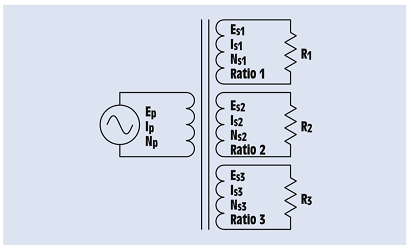
The transformer in the fig 27-17 contains one primary winding and three secondary windings.
The primary is connected to 277 V AC and contains 350 turns of wire.
One secondary has an output voltage of 480 volts and a load resistance of 200 Ω.
Second secondary has an output voltage of 208 volts and a load resistance of 60 Ω.
Third secondary has an output voltage of 120 volts and a load impedance of 24 Ω.
The turns ratio of the first secondary can be found by dividing the smaller voltage into the larger:
The turns ratio of the first secondary is re written as,
The current flow in the first secondary can be calculated using Ohm’s law:
The amount of primary current needed to supply this secondary winding can be found using the turns ratio. As this primary has less voltage, it requires more current:
The number of turns of wire in the first secondary winding is found using the turns ratio. Because this secondary has a higher voltage than the primary, it must have more turns of wire:
The turns ratio of the second secondary winding is found by dividing the higher voltage by the lower:
The turns ratio of the second secondary is re written as,
The amount of current flow in this secondary can be determined using Ohm’s law:
The amount of primary current needed to supply this secondary winding can be found using the turns ratio. As this primary has more voltage, it requires less current:
Because the voltage of this secondary is lesser than the primary, it has less turns of wire than the primary. The number of turns of this secondary is found using the turns ratio:
The turns ratio of the third secondary winding is calculated in the same way as the other two. The larger voltage is divided by the smaller:
The turns ratio of the third secondary is re written as,
The secondary current is found using Ohm’s law:
The amount of primary current needed to supply this secondary winding can be found using the turns ratio. As this primary has more voltage, it requires less current:
Because the voltage of this secondary is lesser than the primary, it has less turns of wire than the primary. The number of turns of this third secondary is found using the turns ratio:
The primary must supply current to each of the three secondary windings. Therefore, the total amount of primary current is the sum of the currents required to supply each secondary:
Want to see more full solutions like this?
Chapter 28 Solutions
Mindtap Electrical, 4 Terms (24 Months) Printed Access Card For Herman's Delmar's Standard Textbook Of Electricity, 6th (mindtap Course List)


- Q2: (30 Marks) Design a DC/DC converter that produce output waveforms that shown in figures below from a fixed DC source of 20 volts. Vo (Volt) 14.1 IL (Amp) 13.9 2.25 1.75 † (msec) Output voltage 0.18 0.2 t (msec) L 0.214 0.22 Output currentarrow_forward6. Build the circuit shown in Figure 2 below in PSpice. Note that the power supply V1 is a VSIN power supply in the SOURCE library. Vcc is a VDC supply found in the SOURCE library. Model this circuit using the Time Domain (Transient) Analysis Type with a Run To Time of 2 ms. A. Paste your output graph showing the voltage at the base terminal, collector terminal and at the load. B. What is the voltage gain of the circuit? (Compare the voltage amplitude at the base terminal input (across Rb2) to that at the collector terminal. C. What happens to the output voltage at the collector terminal if the value of Rb1 is reduced by a factor of 10 (to 14.7 kn)? Simulate this situation and explain the result. D. What happens to the output voltage at the collector terminal if the value of Rb1 is increased by a factor of 3 (to 441 k)? Simulate this situation and explain the result. Rb1 RC 147k 1k C2 C1 Q1 Vcc 1u VOFF = 0 Q2N3904 10Vdc VAMPL = 0.1V1 1u FREQ = 2k R_load Rb2 Re AC = 0 250 40k 20 Figure…arrow_forwardThe input reactance of 1/2 dipole with radius of 1/30 is given as shown in figure below, Assuming the wire of dipole is conductor 5.6*107 S/m, determine at f=1 GHz the a-Loss resistance, b- Radiation efficiency c-Reflection efficiency when the antenna is connected to T.L shown in the figure. Rr Ro= 50 2 1/4 RL -j100 [In(l/a) - 1.5] tan(ẞl)arrow_forward
- 6) For each independent source in this circuit calculate the amount of power being supplied or the amount of power being absorbed + 6V www +3V- www 20 ми ми 352 0.5A + 3Varrow_forward2) A circuit is given as shown (a) Find and label circuit nodes. (b) Determine V, V₂, V₂, I₂ and I. + V₂ 452 m I2 6Ω www 52 t + V + 4A 노동 102 ww 1202 60 www I₂arrow_forwardA Darlington Pair consists of two transistors with the first BJT driving the base terminal of the second transistor as shown in the picture provided. What does the curve trace for a Darlington Pair of Bipolar Junction Transistors look like?arrow_forward
- Provide Pen and paper solution please not using AIarrow_forward5) If the current source supplies 448 watts, then what 15 the value of resistance R? ми R ↑ YA 62 ww 120 } ww 6_02 { wwarrow_forwardWhat is the equivalent resistance of this circuit between terminals A and B ? m 1852 A 7_A 122 도 www 50 ти B ww 36 Ω 201 www www 30√arrow_forward
- 3) A circuit is given as shown. (a) Find and label the circuit nodes. (6) Determine V2, V2, I₂, I₂ and Is © For each circuit element determine how much power it Supplies 15 absorbs. m 20 + 20 www 13 + 20 Z9V H 56 +1 LOV 1/2 1 4A + 3_22 3.2 ми + V₂ I 1arrow_forwardIn this experiment, we are going to use a 2N3904 BJT. Examine the data sheet for this device carefully. In particular, make a note of the current gain (identified by hFE). 1. Obtain the curve trace for a "Darlington Pair" of Bipolar Junction Transistors. A Darlington Pair consists of two transistors with the first BJT driving the base terminal of the second transistor as shown in Figure 1 below. A. Set up the primary sweep voltages for V1 the same as shown in the lecture notes (see the Darlington pair IV curve). B. Set up the secondary sweep currents for 11 to be an order of magnitude smaller than for the single BJT. In the Sweep Type box choose linear and enter the following 3 values: Start Value: 0, End Value: 8u and Increment: 1u (see lecture notes). C. Describe the primary differences you observe between the single BJT Curve Trace and that of the Darlington Pair. Discuss what might cause each difference. Q1 11 Q2 V1 Q2N3904 Figure 1. A Darlington Pair of 2N3904 transistors in a…arrow_forward2. Using the IV plots shown in Fig. 3 (and found in the reintroduction to PSpice) design a BJT biasing circuit that results in the following parameters: VCE = 2 Vand ig = 40 μA. We also require the power supply to be fixed at 5 Volts (this is where the load line intercepts the iB =ic = 0 line). You may use the circuit shown in Example 1. Note that all resistor values in Example 1 must be recalculated. Your solution for the base to ground and base to collector resistors may not be unique.arrow_forward
 Power System Analysis and Design (MindTap Course ...Electrical EngineeringISBN:9781305632134Author:J. Duncan Glover, Thomas Overbye, Mulukutla S. SarmaPublisher:Cengage Learning