Student Workbook for Physics for Scientists and Engineers: A Strategic Approach, Vol 1. (Chs 1-21)
4th Edition
ISBN: 9780134110646
Author: Randall D. Knight (Professor Emeritus)
Publisher: PEARSON
expand_more
expand_more
format_list_bulleted
Textbook Question
Chapter 28, Problem 3CQ
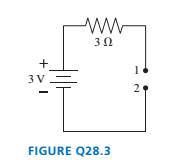
The wire is broken on the right side of the circuit in FIGURE Q28.3. What is the potential difference

Expert Solution & Answer
Want to see the full answer?
Check out a sample textbook solution
Students have asked these similar questions
A box is dropped on a level conveyor belt that is moving at 4.5 m/s in the +x direction in a shipping facility. The box/belt friction coefficient is 0.15. For what duration will the box slide on the belt? In which direction does the friction force act on the box? How far will the box have moved horizontally by the time it stops sliding along the belt?
No chatgpt pls will upvote
No chatgpt pls will upvote
Chapter 28 Solutions
Student Workbook for Physics for Scientists and Engineers: A Strategic Approach, Vol 1. (Chs 1-21)
Ch. 28 - Rank in order, from largest to smallest, the...Ch. 28 - The tip of a flashlight bulb is touching the top...Ch. 28 - The wire is broken on the right side of the...Ch. 28 - The circuit of FIGURE Q28.4 has two resistors,...Ch. 28 - The circuit of FIGURE Q28.5 has two resistors,...Ch. 28 - Rank in order, from largest to smallest, the...Ch. 28 - Are the two resistors in FIGURE Q28.7 in series or...Ch. 28 - A battery with internal resistance r is connected...Ch. 28 - Initially bulbs A and B in FIGURE Q28.9 are...Ch. 28 - Bulbs A. B, and C in FIGURE Q28.1O axe identical,...
Ch. 28 - Bulbs A and B in FIGURE Q28.11 are identical, and...Ch. 28 - Prob. 12CQCh. 28 - FIGURE Q28.13 shows the voltage as a function of...Ch. 28 - Prob. 1EAPCh. 28 - Draw a circuit diagram for the circuit of FIGURE...Ch. 28 - Prob. 3EAPCh. 28 - Prob. 4EAPCh. 28 - a. What are the magnitude and direction of the...Ch. 28 - What is the magnitude of the potential difference...Ch. 28 - Prob. 7EAPCh. 28 - Prob. 8EAPCh. 28 - A 60 W lightbulb and a 100 W lightbulb are placed...Ch. 28 - Prob. 10EAPCh. 28 - The five identical bulbs in FIGURE EX2B.11 are all...Ch. 28 - Prob. 12EAPCh. 28 - Prob. 13EAPCh. 28 - A typical American family uses kWh of electricity...Ch. 28 - A waterbed heater uses 450 W of power. It is on 25...Ch. 28 - Prob. 16EAPCh. 28 - Prob. 17EAPCh. 28 - Prob. 18EAPCh. 28 - 19. The voltage across the terminals of a V...Ch. 28 - Prob. 20EAPCh. 28 - Prob. 21EAPCh. 28 - 22. Two of the three resistors in FIGURE EX28.22...Ch. 28 - What is the value of resistor R in FIGURE EX28.23?Ch. 28 - Prob. 24EAPCh. 28 - What is the equivalent resistance between points a...Ch. 28 - What is the equivalent resistance between points a...Ch. 28 - Prob. 27EAPCh. 28 - Prob. 28EAPCh. 28 - Prob. 29EAPCh. 28 - Prob. 30EAPCh. 28 - Prob. 31EAPCh. 28 - Prob. 32EAPCh. 28 - Prob. 33EAPCh. 28 - What is the time constant for the discharge of the...Ch. 28 - A 10F capacitor initially charged to 20C is...Ch. 28 - Prob. 36EAPCh. 28 - Prob. 37EAPCh. 28 - A capacitor is discharged through a resistor. The...Ch. 28 - Prob. 39EAPCh. 28 - 40. A refrigerator has a 1000 W compressor, but...Ch. 28 - Prob. 41EAPCh. 28 - An electric eel develops a potential difference...Ch. 28 - You have a resistor, a resistor, a resistor, and a...Ch. 28 - A 2.0 -m-long, 1.0 -mm-diameter wire has a...Ch. 28 - What is the equivalent resistance between points a...Ch. 28 - What are the emf and internal resistance of the...Ch. 28 - A string of holiday lights can be wired in series,...Ch. 28 - The circuit shown in FIGURE P28.48 is inside a 15...Ch. 28 - Suppose you have resistors 2.5,3.5, and 4.5 and a...Ch. 28 - A lightbulb is in series with a resistor. The...Ch. 28 - Prob. 51EAPCh. 28 - Prob. 52EAPCh. 28 - Prob. 53EAPCh. 28 - Prob. 54EAPCh. 28 - What are the battery current Ibatand the potential...Ch. 28 - A battery is a voltage source, always providing...Ch. 28 - A circuit you’re building needs an ammeter that...Ch. 28 - For the circuit shown in FIGURE P28.58, find the...Ch. 28 - For the circuit shown in FIGURE P28.59, find the...Ch. 28 - For the circuit shown in FIGURE P28.60, find the...Ch. 28 - What is the current through the 20 resistor in...Ch. 28 - For the circuit shown in FIGURE P28.62, find the...Ch. 28 - What is the current through the 10 resistor in...Ch. 28 - For what emf does the 200 resistor in FIGURE...Ch. 28 - Prob. 65EAPCh. 28 - Prob. 66EAPCh. 28 - Prob. 67EAPCh. 28 - II A circuit you're using discharges a 20F...Ch. 28 - A 150F defibrillator capacitor is charged to 1500V...Ch. 28 - Prob. 70EAPCh. 28 - A 0.25F capacitor is charged to 50 V. It is then...Ch. 28 - Prob. 72EAPCh. 28 - Prob. 73EAPCh. 28 - The capacitors in FIGURE P28.74 are charged and...Ch. 28 - Prob. 75EAPCh. 28 - Prob. 76EAPCh. 28 - Prob. 77EAPCh. 28 - Prob. 78EAPCh. 28 - Prob. 79EAPCh. 28 - Prob. 80EAPCh. 28 - Prob. 81EAPCh. 28 - Prob. 82EAP
Knowledge Booster
Learn more about
Need a deep-dive on the concept behind this application? Look no further. Learn more about this topic, physics and related others by exploring similar questions and additional content below.Similar questions
- A toy car speeds up at 1.0 m/s2 while rolling down a ramp, and slows down at a rate of 2.0 m/s2 while rolling up the same ramp. What is the slope of the ramp in degrees? Grade in %? The friction coefficient?arrow_forwardPlz solution should be complete No chatgpt pls will upvote .arrow_forwardA box with friction coefficient of 0.2 rests on a 12 foot long plank of wood. How high (in feet) must one side of the plank be lifted in order for the box to begin to slide?arrow_forward
- A hydrogen atom has just a single electron orbiting the nucleus, which happens to be a single proton without any neutrons. The proton is positively charged, the electron negatively, but both with the same magnitude of charge given by e=1.602x10⁻¹⁹C. The mass of an electron is 9.11x10⁻³¹kg, and the proton is 1.67x10⁻²⁷kg. Find the ratio of the electrostatic to the gravitational force of attraction between the electron and the proton in hydrogen. \arrow_forwardWhat is the third law pair to the normal force as you sit in a chair? What effect does the sun's pull on earth have in terms of third law pairs?arrow_forwardUsing Newton's 2nd law, show that all objects subject to the pull of gravity alone should fall at the same rate. What is that rate?arrow_forward
- No chatgpt pls will upvotearrow_forwardA cart on wheels (assume frictionless) with a mass of 20 kg is pulled rightward with a 50N force. What is its acceleration?arrow_forwardLight travels through a vacuum at a speed of 2.998 x 10⁸m/s. Determine the speed of light in the following media: crown glass (n = 1.52)arrow_forward
arrow_back_ios
SEE MORE QUESTIONS
arrow_forward_ios
Recommended textbooks for you
 Physics for Scientists and EngineersPhysicsISBN:9781337553278Author:Raymond A. Serway, John W. JewettPublisher:Cengage Learning
 Physics for Scientists and Engineers with Modern ...PhysicsISBN:9781337553292Author:Raymond A. Serway, John W. JewettPublisher:Cengage Learning
 Physics for Scientists and Engineers: Foundations...PhysicsISBN:9781133939146Author:Katz, Debora M.Publisher:Cengage Learning
 Principles of Physics: A Calculus-Based TextPhysicsISBN:9781133104261Author:Raymond A. Serway, John W. JewettPublisher:Cengage Learning
 Physics for Scientists and Engineers, Technology ...PhysicsISBN:9781305116399Author:Raymond A. Serway, John W. JewettPublisher:Cengage Learning

Physics for Scientists and Engineers
Physics
ISBN:9781337553278
Author:Raymond A. Serway, John W. Jewett
Publisher:Cengage Learning

Physics for Scientists and Engineers with Modern ...
Physics
ISBN:9781337553292
Author:Raymond A. Serway, John W. Jewett
Publisher:Cengage Learning

Physics for Scientists and Engineers: Foundations...
Physics
ISBN:9781133939146
Author:Katz, Debora M.
Publisher:Cengage Learning

Principles of Physics: A Calculus-Based Text
Physics
ISBN:9781133104261
Author:Raymond A. Serway, John W. Jewett
Publisher:Cengage Learning

Physics for Scientists and Engineers, Technology ...
Physics
ISBN:9781305116399
Author:Raymond A. Serway, John W. Jewett
Publisher:Cengage Learning

DC Series circuits explained - The basics working principle; Author: The Engineering Mindset;https://www.youtube.com/watch?v=VV6tZ3Aqfuc;License: Standard YouTube License, CC-BY