
Videos
(a)
The flux graph through the loop.
(a)
Answer to Problem 39P
The flux graph through the loop as a function of time is shown in figure 1.
Explanation of Solution
Given:
The length of the rectangular loop,
The widthof the rectangular loop,
The stance of the rectangular loop,
The speed of the rectangular loop,
The magnetic field of the rectangular loop,
Formula used:
The formula for flux through the loop as a function of time is given by,
The expression for the time required to enter into uniform magnetic field is given by,
The expression of flux in terms of the length is given by,
Calculation:
The time required to enter into uniform magnetic field is calculated as,
The flux
For,
For,
From equation (1) and (2)
Now,
The induced current through the loop as a function of time is shown in figure 1.
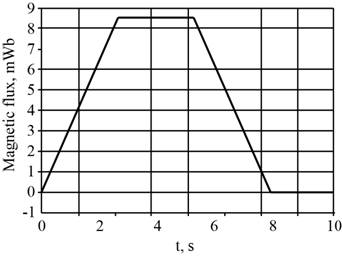
Figure 1
Conclusion:
The graph of induced emf through the loop as a function of time is shown in the figure 1.
(b)
The graph of induced emf and current through the loop.
(b)
Answer to Problem 39P
The graph of induced emf and current through the loop is shown in the figure 2 and 3.
Explanation of Solution
Formula used:
The formula for induced emfthrough the loop is given by,
Calculation:
The induced emf through the loop when
Theinduced emfthrough the loop when
The current through the loop when
The graph for the emf is shown in figure 2.
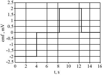
Figure 2
The expression for the value of current is given by,
The graph for the current is shown in figure 3.
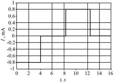
Figure 3
Conclusion:
The graph of induced emfand current through the loop is shown in the figure 2 and 3.
Want to see more full solutions like this?
Chapter 28 Solutions
Physics for Scientists and Engineers


- O Macmillan Learning The mass of a particular eagle is twice that of a hunted pigeon. Suppose the pigeon is flying north at Vi2 = 16.1 m/s when the eagle swoops down, grabs the pigeon, and flies off. At the instant right before the attack, the eagle is flying toward the pigeon at an angle 0 = 64.3° below the horizontal and a speed of Vi,1 = 37.9 m/s. What is the speed of of the eagle immediately after it catches its prey? What is the magnitude & of the angle, measured from horizontal, at which the eagle is flying immediately after the strike? Uf = II x10 TOOLS Vi.1 Vi,2 m/sarrow_forwardWhat is the equivalent resistance if you connect a 1.7 Ohm, a 9.3 Ohm, and a 22 Ohm resistor in series? (Give your answer as the number of Ohms.)arrow_forwardThree wires meet at a junction. One wire carries a current of 5.2 Amps into the junction, and a second wire carries a current of 3.7 Amps out of the junction. What is the current in the third wire? Give your answer as the number of Amps, and give a positive number if the current in that wire flows out of the junction, or a negative number if the current in that wire flows into the junction.arrow_forward
- What is the equivalent resistance if you connect a 4.5 Ohm, a 6.8 Ohm, and a 15 Ohm resistor in parallel? (Give your answer as the number of Ohms.)arrow_forwardSuppose a heart defibrillator passes 10.5 Amps of current through a patient's torso for 5.0 x 10⁻³ seconds in order to restore a regular heartbeat. The voltage across the defibrillator is 9800 volts for the entire time that current is flowing. If 7.25 kg of body tissue is involved, with a specific heat of 3500 J/(kg°C), then what is the resulting temperature increase of the person's torso? (Give your answer as the number of degrees C.)arrow_forwardThe figure below is a cross-sectional view of a coaxial cable. The center conductor is surrounded by a rubber layer, an outer conductor, and another rubber layer. In a particular application, the current in the inner conductor is I₁ = 1.04 A out of the page and the current in the outer conductor is I2 = 2.90 A into the page. Assuming the distance d = 1.00 mm, answer the following. 4 12 (a) Determine the magnitude and direction of the magnetic field at point a. magnitude 208 direction upward (b) Determine the magnitude and direction of the magnetic field at point b. magnitude direction 238 You can approach this problem by finding the field produced by current I₁ and the field produced by I2 and then adding them vectorially. μT downwardarrow_forward
- Shoto, from My Hero Academia, has a power (or a “quirk”) that allows him to make large amounts of ice from nothing. Let us say that due to a fire a 361 kg steel beam is heated to 943.˚C and Shoto creates 390. kg of ice at 0.00˚C around it to cool it down. What is the final temperature of the system after the ice melts and it reaches thermal equilibrium? The specific heat of steel is 502 J/kg˚C. The specific heat of water is 4186 J/kg˚C. The latent heat of fusion for ice is 3.33⋅10^5 J/kg.arrow_forwardA 25.0 cm long organ pipe is filled with air and is open at one end and closed at the other. The speed of sound in air at 0°C is 331 m/s. What is the frequency of the fourth mode of vibration? Multiple Choice О 1,550 Hz О 1,750 Hz О 2,320 Hz О 2,720 Hz О 3,170 Hzarrow_forward23.4 g of coffee beans at room temperature (18.6 °C) is mixed into 316 g of water at 96.8 °C in an effort to make coffee. The entire system is poured in a 363 g ceramic mug. Assume the mug is initally also at room temperature (18.6 °C). What is the final temperature of the mixture? The specific heat of ground coffee beans is 1670 J/kg˚C, the specific heat of water is 4186 J/kg˚C, and the specific heat of the mug is 850. J/kg˚C.arrow_forward
- Snoop Dogg, in an effort to get laid back (with his mind on his money and his money on his mind) pours himself a gin and juice. He mixes 0.124 kg (about 3 shots) of gin with 0.576 kg (about a pint) of orange juice. The gin starts at 20.0˚C, room temperature. The juice is refrigerated and starts at 2.89 ˚C. What is the final temperature after mixing of the gin and juice? The specific heat of gin is 3460 J/kg˚C and the specific heat of orange juice is 3730 J/kg˚C.arrow_forwardA sword is heated up to 226 °C, it is put into a nearby barrel of water that is at 18.4 °C. What mass of water would be needed to cool the sword to 30.0˚C, bringing the system to thermal equilibrium? The sword is 35.4 kg and is made of steel. The specific heat of water is = 4186 J/kg ˚C. The specific heat of steel is = 502 J/kg ˚Carrow_forwardYou are planning on installing a new above-ground swimming pool in your backyard. The pool will be rectangular with dimensions 32.0 m x 10.0 m. It will be filled with fresh water to a depth of 2.20 m. In order to provide the appropriate structural support, you wish to determine the following. (a) Determine the force exerted on the bottom of the pool by the water (in N). (No Response) N (b) Determine the force exerted on each end of the pool by the water (in N). (Assume the end is the 10.0 m wall.) (No Response) N (c) Determine the force exerted on each side of the pool by the water (in N). (Assume the side is the 32.0 m wall.) (No Response) N (d) You wish to have swimming parties with your children and grandchildren. At a given time, you might have 23 people with an average mass of 75.0 kg in the pool. You need to determine if such parties will affect your calculations for the required strength of materials supporting your pool. The parties will not affect the required strength since…arrow_forward

 Glencoe Physics: Principles and Problems, Student...PhysicsISBN:9780078807213Author:Paul W. ZitzewitzPublisher:Glencoe/McGraw-Hill
 Physics for Scientists and Engineers: Foundations...PhysicsISBN:9781133939146Author:Katz, Debora M.Publisher:Cengage Learning
 Principles of Physics: A Calculus-Based TextPhysicsISBN:9781133104261Author:Raymond A. Serway, John W. JewettPublisher:Cengage Learning
 Physics for Scientists and Engineers with Modern ...PhysicsISBN:9781337553292Author:Raymond A. Serway, John W. JewettPublisher:Cengage Learning
 College PhysicsPhysicsISBN:9781938168000Author:Paul Peter Urone, Roger HinrichsPublisher:OpenStax College