
Concept explainers
Videos
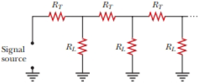
Figure P27.48 shows a circuit model for the transmission of an electrical signal such as cable TV to a large number of subscribers. Each subscriber connects a load resistance RL between the transmission line and the ground. The ground is assumed to be at zero potential and able to carry any current between any ground connections with negligible resistance. The resistance of the transmission line between the connection points of different subscribers is modeled as the constant resistance RT. Show that the equivalent resistance across the signal source is
Suggestion: Because the number of subscribers is large, the equivalent resistance would not change noticeably if the first subscriber canceled the service. Consequently, the equivalent resistance of the section of the circuit to the right of the first load resistor is nearly equal to Req.
Figure P27.48
Want to see the full answer?
Check out a sample textbook solution
Chapter 28 Solutions
EBK PHYSICS FOR SCIENTISTS AND ENGINEER


- In the comics Thor flies by spinning his hammer really fast from a leather strap at the end of the handle, letting go, then grabbing it and having it pull him. If Thor wants to reach escape velocity (velocity needed to leave Earth’s atmosphere), he will need the linear velocity of the center of mass of the hammer to be 11,200 m/s. A) If the distance from the end of the strap to the center of the hammer is 0.334 m, what angular velocity does Thor need to spin his hammer at to reach escape velocity? b) If the hammer starts from rest what angular acceleration does Thor need to reach that angular velocity in 4.16 s? c) While the hammer is spinning at its maximum speed what impossibly large tension does the leather strap, which the hammer is spinning by, exert when the hammer is at its lowest point? The hammer has a total mass of 20.0kg.arrow_forwardThe car goes from driving straight to spinning at 10.6 rev/min in 0.257 s with a radius of 12.2 m. The angular accleration is 4.28 rad/s^2. During this flip Barbie stays firmly seated in the car’s seat. Barbie has a mass of 58.0 kg, what is her normal force at the top of the loop?arrow_forwardConsider a hoop of radius R and mass M rolling without slipping. Which form of kinetic energy is larger, translational or rotational?arrow_forward
- A roller-coaster vehicle has a mass of 571 kg when fully loaded with passengers (see figure). A) If the vehicle has a speed of 22.5 m/s at point A, what is the force of the track on the vehicle at this point? B) What is the maximum speed the vehicle can have at point B, in order for gravity to hold it on the track?arrow_forwardThis one wheeled motorcycle’s wheel maximum angular velocity was about 430 rev/min. Given that it’s radius was 0.920 m, what was the largest linear velocity of the monowheel?The monowheel could not accelerate fast or the rider would start spinning inside (this is called "gerbiling"). The maximum angular acceleration was 10.9 rad/s2. How long, in seconds, would it take it to hit maximum speed from rest?arrow_forwardIf points a and b are connected by a wire with negligible resistance, find the magnitude of the current in the 12.0 V battery.arrow_forward
- Consider the two pucks shown in the figure. As they move towards each other, the momentum of each puck is equal in magnitude and opposite in direction. Given that v kinetic energy of the system is converted to internal energy? 30.0° 130.0 = green 11.0 m/s, and m blue is 25.0% greater than m 'green' what are the final speeds of each puck (in m/s), if 1½-½ t thearrow_forwardConsider the blocks on the curved ramp as seen in the figure. The blocks have masses m₁ = 2.00 kg and m₂ = 3.60 kg, and are initially at rest. The blocks are allowed to slide down the ramp and they then undergo a head-on, elastic collision on the flat portion. Determine the heights (in m) to which m₁ and m2 rise on the curved portion of the ramp after the collision. Assume the ramp is frictionless, and h 4.40 m. m2 = m₁ m hm1 hm2 m iarrow_forwardA 3.04-kg steel ball strikes a massive wall at 10.0 m/s at an angle of 0 = 60.0° with the plane of the wall. It bounces off the wall with the same speed and angle (see the figure below). If the ball is in contact with the wall for 0.234 s, what is the average force exerted by the wall on the ball? magnitude direction ---Select--- ✓ N xarrow_forward
- You are in the early stages of an internship at NASA. Your supervisor has asked you to analyze emergency procedures for extravehicular activity (EVA), when the astronauts leave the International Space Station (ISS) to do repairs to its exterior or perform other tasks. In particular, the scenario you are studying is a failure of the manned-maneuvering unit (MMU), which is a nitrogen-propelled backpack that attaches to the astronaut's primary life support system (PLSS). In this scenario, the astronaut is floating directly away from the ISS and cannot use the failed MMU to get back. Therefore, the emergency plan is to take off the MMU and throw it in a direction directly away from the ISS, an action that will hopefully cause the astronaut to reverse direction and float back to the station. You have the following mass data provided to you: astronaut: 78.1 kg, spacesuit: 36.8 kg, MMU: 115 kg, PLSS: 145 kg. Based on tests performed by astronauts floating "weightless" inside the ISS, the most…arrow_forwardThree carts of masses m₁ = 4.50 kg, m₂ = 10.50 kg, and m3 = 3.00 kg move on a frictionless, horizontal track with speeds of V1 v1 13 m 12 mq m3 (a) Find the final velocity of the train of three carts. magnitude direction m/s |---Select--- ☑ (b) Does your answer require that all the carts collide and stick together at the same moment? ○ Yes Ο Νο = 6.00 m/s to the right, v₂ = 3.00 m/s to the right, and V3 = 6.00 m/s to the left, as shown below. Velcro couplers make the carts stick together after colliding.arrow_forwardA girl launches a toy rocket from the ground. The engine experiences an average thrust of 5.26 N. The mass of the engine plus fuel before liftoff is 25.4 g, which includes fuel mass of 12.7 g. The engine fires for a total of 1.90 s. (Assume all the fuel is consumed.) (a) Calculate the average exhaust speed of the engine (in m/s). m/s (b) This engine is positioned in a rocket body of mass 70.0 g. What is the magnitude of the final velocity of the rocket (in m/s) if it were to be fired from rest in outer space with the same amount of fuel? Assume the fuel burns at a constant rate. m/sarrow_forward
 Physics for Scientists and Engineers: Foundations...PhysicsISBN:9781133939146Author:Katz, Debora M.Publisher:Cengage Learning
 Physics for Scientists and EngineersPhysicsISBN:9781337553278Author:Raymond A. Serway, John W. JewettPublisher:Cengage Learning
 Physics for Scientists and Engineers with Modern ...PhysicsISBN:9781337553292Author:Raymond A. Serway, John W. JewettPublisher:Cengage Learning
 Principles of Physics: A Calculus-Based TextPhysicsISBN:9781133104261Author:Raymond A. Serway, John W. JewettPublisher:Cengage Learning
 Physics for Scientists and Engineers, Technology ...PhysicsISBN:9781305116399Author:Raymond A. Serway, John W. JewettPublisher:Cengage Learning