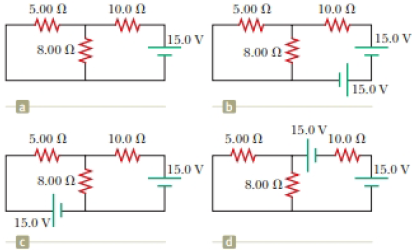
The circuit in Figure P27.34a consists of three resistors and one battery with no internal resistance. (a) Find the current in the 5.00-Ω resistor. (b) Find the power delivered to the 5.00-Ω resistor. (c) In each of the circuits in Figures P27.34b, P27.34c, and P27.34d, an additional 15.0-V battery has been inserted into the circuit. Which diagram or diagrams represent a circuit that requires the use of Kirchhoff’s rules to find the currents? Explain why. (d) In which of these three new circuits is the smallest amount of power delivered to the 10.0-Ω resistor? (You need not calculate the power in each circuit if you explain your answer.) Figure P27.34
The circuit in Figure P27.34a consists of three resistors and one battery with no internal resistance. (a) Find the current in the 5.00-Ω resistor. (b) Find the power delivered to the 5.00-Ω resistor. (c) In each of the circuits in Figures P27.34b, P27.34c, and P27.34d, an additional 15.0-V battery has been inserted into the circuit. Which diagram or diagrams represent a circuit that requires the use of Kirchhoff’s rules to find the currents? Explain why. (d) In which of these three new circuits is the smallest amount of power delivered to the 10.0-Ω resistor? (You need not calculate the power in each circuit if you explain your answer.) Figure P27.34
Solution Summary: The author calculates the resistance across the circuit when resistors R_P is connected in parallel combination.
The circuit in Figure P27.34a consists of three resistors and one battery with no internal resistance. (a) Find the current in the 5.00-Ω resistor. (b) Find the power delivered to the 5.00-Ω resistor. (c) In each of the circuits in Figures P27.34b, P27.34c, and P27.34d, an additional 15.0-V battery has been inserted into the circuit. Which diagram or diagrams represent a circuit that requires the use of Kirchhoff’s rules to find the currents? Explain why. (d) In which of these three new circuits is the smallest amount of power delivered to the 10.0-Ω resistor? (You need not calculate the power in each circuit if you explain your answer.)
4.) The diagram shows the electric field lines of a positively charged conducting sphere of
radius R and charge Q.
A
B
Points A and B are located on the same field line.
A proton is placed at A and released from rest. The magnitude of the work done by the electric field in
moving the proton from A to B is 1.7×10⁻¹⁶ J. Point A is at a distance of 5.0×10⁻²m from the centre of
the sphere. Point B is at a distance of 1.0×10⁻¹ m from the centre of the sphere.
(a) Explain why the electric potential decreases from A to B. [2]
(b) Draw, on the axes, the variation of electric potential V with distance r from the centre of the
sphere.
R
[2]
(c(i)) Calculate the electric potential difference between points A and B. [1]
(c(ii)) Determine the charge Q of the sphere. [2]
(d) The concept of potential is also used in the context of gravitational fields. Suggest why scientists
developed a common terminology to describe different types of fields. [1]
3.) The graph shows how current I varies with potential difference V across a component X.
904
80-
70-
60-
50-
I/MA
40-
30-
20-
10-
0+
0
0.5
1.0 1.5 2.0 2.5 3.0 3.5 4.0 4.5 5.0
VIV
Component X and a cell of negligible internal resistance are placed in a circuit.
A variable resistor R is connected in series with component X. The ammeter reads 20mA.
4.0V
4.0V
Component X and the cell are now placed in a potential divider circuit.
(a) Outline why component X is considered non-ohmic. [1]
(b(i)) Determine the resistance of the variable resistor. [3]
(b(ii)) Calculate the power dissipated in the circuit. [1]
(c(i)) State the range of current that the ammeter can measure as the slider S of the potential divider
is moved from Q to P. [1]
(c(ii)) Describe, by reference to your answer for (c)(i), the advantage of the potential divider
arrangement over the arrangement in (b).
1.) Two long parallel current-carrying wires P and Q are separated by 0.10 m. The current in wire P is 5.0 A.
The magnetic force on a length of 0.50 m of wire P due to the current in wire Q is 2.0 × 10-s N.
(a) State and explain the magnitude of the force on a length of 0.50 m of wire Q due to the current in P. [2]
(b) Calculate the current in wire Q. [2]
(c) Another current-carrying wire R is placed parallel to wires P and Q and halfway between them as shown.
wire P
wire R
wire Q
0.05 m
0.05 m
The net magnetic force on wire Q is now zero.
(c.i) State the direction of the current in R, relative to the current in P.[1]
(c.ii) Deduce the current in R. [2]
Chapter 28 Solutions
Physics for Scientists and Engineers, Technology Update, Hybrid Edition (with Enhanced WebAssign Multi-Term LOE Printed Access Card for Physics)
Need a deep-dive on the concept behind this application? Look no further. Learn more about this topic, physics and related others by exploring similar questions and additional content below.
How To Solve Any Resistors In Series and Parallel Combination Circuit Problems in Physics; Author: The Organic Chemistry Tutor;https://www.youtube.com/watch?v=eFlJy0cPbsY;License: Standard YouTube License, CC-BY


 Physics for Scientists and Engineers: Foundations...PhysicsISBN:9781133939146Author:Katz, Debora M.Publisher:Cengage Learning
 Principles of Physics: A Calculus-Based TextPhysicsISBN:9781133104261Author:Raymond A. Serway, John W. JewettPublisher:Cengage Learning
 College PhysicsPhysicsISBN:9781305952300Author:Raymond A. Serway, Chris VuillePublisher:Cengage Learning
 College PhysicsPhysicsISBN:9781285737027Author:Raymond A. Serway, Chris VuillePublisher:Cengage Learning
 Physics for Scientists and Engineers, Technology ...PhysicsISBN:9781305116399Author:Raymond A. Serway, John W. JewettPublisher:Cengage Learning
 Physics for Scientists and Engineers with Modern ...PhysicsISBN:9781337553292Author:Raymond A. Serway, John W. JewettPublisher:Cengage Learning