ENGINEERING DESIGN PROCESS
3rd Edition
ISBN: 9781305253285
Author: HAIK
Publisher: CENGAGE L
expand_more
expand_more
format_list_bulleted
Concept explainers
Videos
Textbook Question
Chapter 2.8, Problem 1P
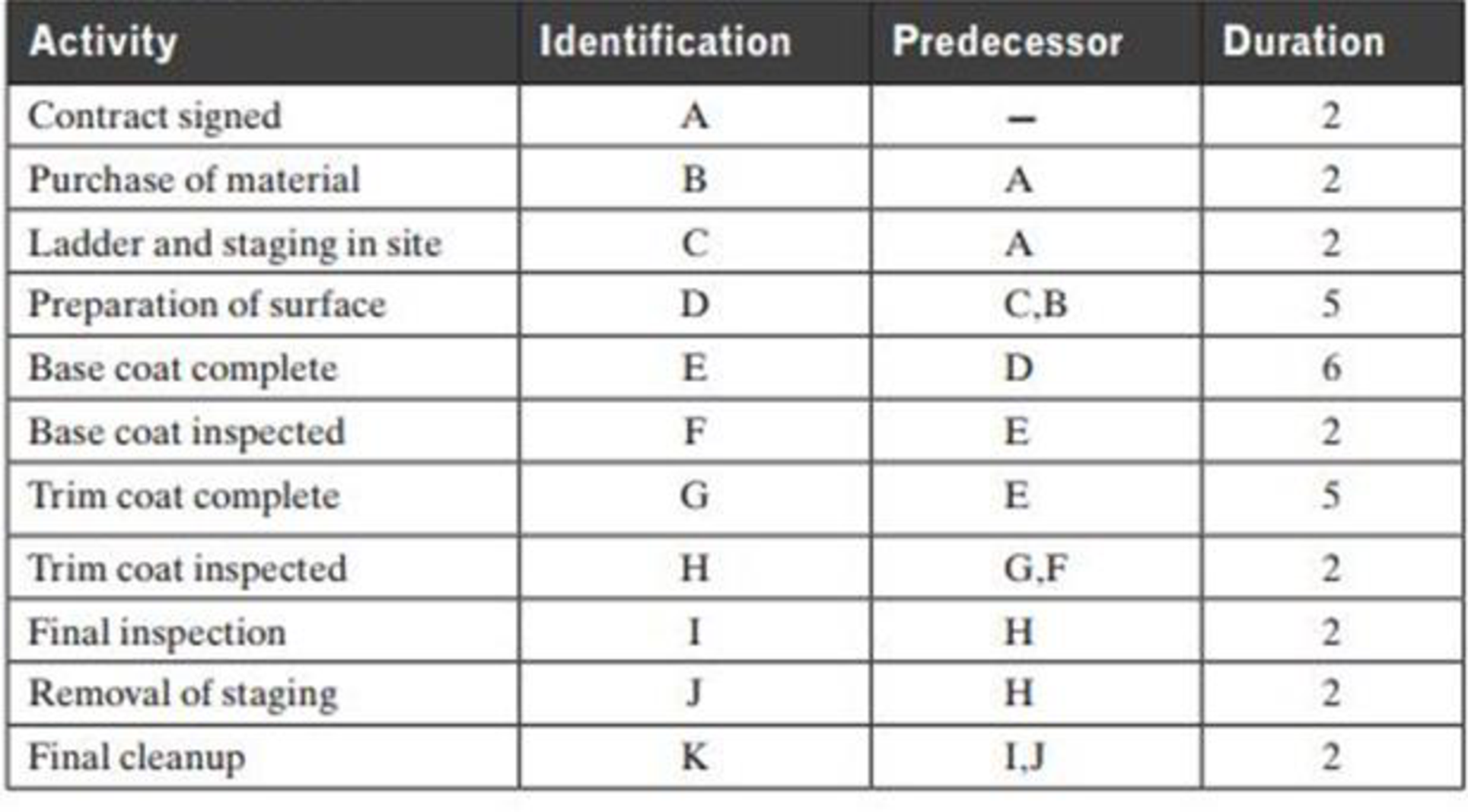
Table 2.3 breaks down the number of major jobs or activities involved in painting a two-story house.
- a. Develop a CPM network.
- b. Determine the critical path of the network.
- c. Determine the expected project’s duration time period.
Table 2.3: Problem 1
(a)
Expert Solution
To determine
A CPM network.
Explanation of Solution
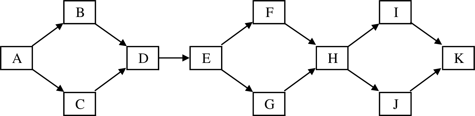
The CPM network for the data given in the Table 2.3 is shown below:
(b)
Expert Solution
To determine
The critical path of the network.
Answer to Problem 1P
The critical path activities are as follows.
| Critical Paths |
| A-B-D-E-G-H-I-K |
| A-B-D-E-G-H-J-K |
| A-C-D-E-G-H-I-K |
| A-C-D-E-G-H-J-K |
Explanation of Solution
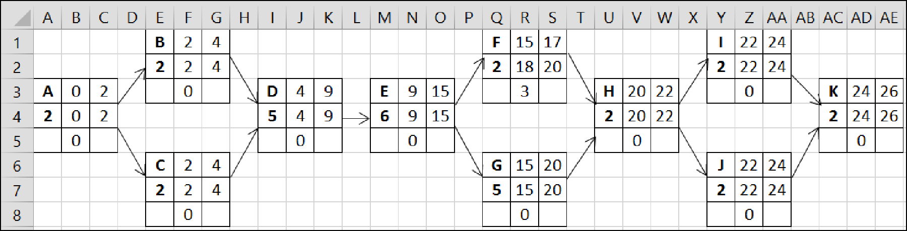
Using Excel spread sheet the network path is framed and its critical path is identified and shown below:
| Activity | Early Start Time | Early Finish Time |
| Duration | Late Start Time | Late Finish Time |
| Float/Slack |
Formula:
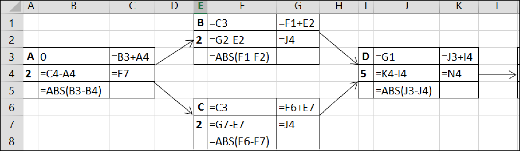
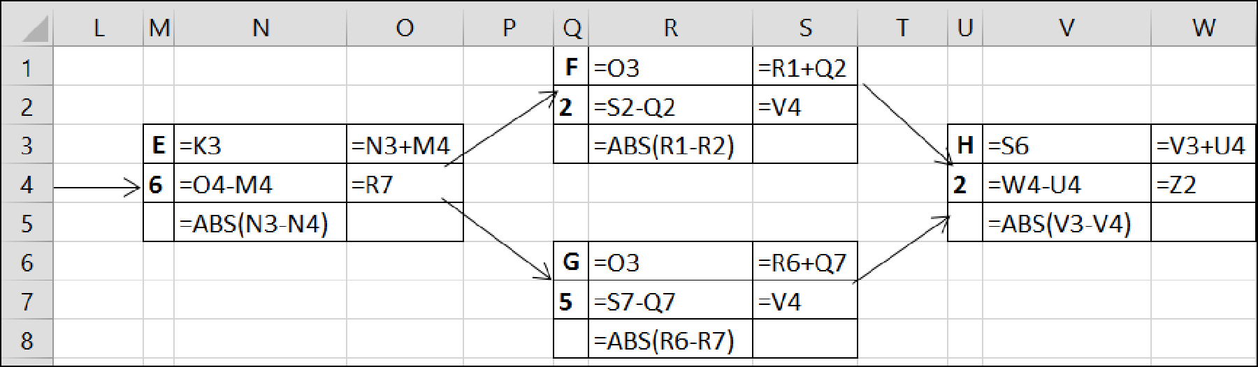
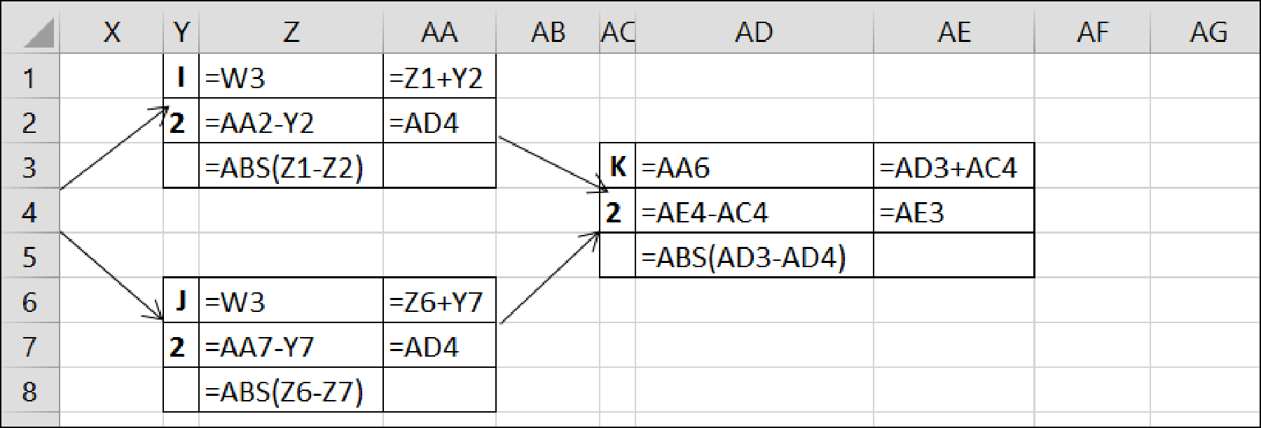
The identified network paths are shown below with duration:
| Paths | Duration |
| A-B-D-E-F-H-J-K | 23 |
| A-B-D-E-G-H-I-K | 26 |
| A-B-D-E-G-H-J-K | 26 |
| A-C-D-E-F-H-I-K | 23 |
| A-C-D-E-F-H-J-K | 23 |
| A-C-D-E-G-H-I-K | 26 |
| A-C-D-E-G-H-J-K | 26 |
The path with the longest duration is the critical path. Hence, the critical path activities are as follows.
| Critical Paths |
| A-B-D-E-G-H-I-K |
| A-B-D-E-G-H-J-K |
| A-C-D-E-G-H-I-K |
| A-C-D-E-G-H-J-K |
(c)
Expert Solution
To determine
The expected project duration time.
Explanation of Solution
Refer part (b)
The expected project duration time is shown below:
| Paths | Duration |
| A-B-D-E-G-H-I-K | 26 |
| A-B-D-E-G-H-J-K | 26 |
| A-C-D-E-G-H-I-K | 26 |
| A-C-D-E-G-H-J-K | 26 |
Want to see more full solutions like this?
Subscribe now to access step-by-step solutions to millions of textbook problems written by subject matter experts!
Students have asked these similar questions
using the theorem of three moments, find all the moments, I need concise calculations only
Practise question need help on
Can you show explaination and working. The answer from the text book is Q=5.03 X 10^-3
Knowledge Booster


Learn more about
Need a deep-dive on the concept behind this application? Look no further. Learn more about this topic, mechanical-engineering and related others by exploring similar questions and additional content below.Similar questions
- practise questionarrow_forwardCan you provide steps and an explaination on how the height value to calculate the Pressure at point B is (-5-3.5) and the solution is 86.4kPa.arrow_forwardPROBLEM 3.46 The solid cylindrical rod BC of length L = 600 mm is attached to the rigid lever AB of length a = 380 mm and to the support at C. When a 500 N force P is applied at A, design specifications require that the displacement of A not exceed 25 mm when a 500 N force P is applied at A For the material indicated determine the required diameter of the rod. Aluminium: Tall = 65 MPa, G = 27 GPa. Aarrow_forward
- Find the equivalent mass of the rocker arm assembly with respect to the x coordinate. k₁ mi m2 k₁arrow_forward2. Figure below shows a U-tube manometer open at both ends and containing a column of liquid mercury of length l and specific weight y. Considering a small displacement x of the manometer meniscus from its equilibrium position (or datum), determine the equivalent spring constant associated with the restoring force. Datum Area, Aarrow_forward1. The consequences of a head-on collision of two automobiles can be studied by considering the impact of the automobile on a barrier, as shown in figure below. Construct a mathematical model (i.e., draw the diagram) by considering the masses of the automobile body, engine, transmission, and suspension and the elasticity of the bumpers, radiator, sheet metal body, driveline, and engine mounts.arrow_forward
- 3.) 15.40 – Collar B moves up at constant velocity vB = 1.5 m/s. Rod AB has length = 1.2 m. The incline is at angle = 25°. Compute an expression for the angular velocity of rod AB, ė and the velocity of end A of the rod (✓✓) as a function of v₂,1,0,0. Then compute numerical answers for ȧ & y_ with 0 = 50°.arrow_forward2.) 15.12 The assembly shown consists of the straight rod ABC which passes through and is welded to the grectangular plate DEFH. The assembly rotates about the axis AC with a constant angular velocity of 9 rad/s. Knowing that the motion when viewed from C is counterclockwise, determine the velocity and acceleration of corner F.arrow_forward500 Q3: The attachment shown in Fig.3 is made of 1040 HR. The static force is 30 kN. Specify the weldment (give the pattern, electrode number, type of weld, length of weld, and leg size). Fig. 3 All dimension in mm 30 kN 100 (10 Marks)arrow_forward
- (read image) (answer given)arrow_forwardA cylinder and a disk are used as pulleys, as shown in the figure. Using the data given in the figure, if a body of mass m = 3 kg is released from rest after falling a height h 1.5 m, find: a) The velocity of the body. b) The angular velocity of the disk. c) The number of revolutions the cylinder has made. T₁ F Rd = 0.2 m md = 2 kg T T₂1 Rc = 0.4 m mc = 5 kg ☐ m = 3 kgarrow_forward(read image) (answer given)arrow_forward
arrow_back_ios
SEE MORE QUESTIONS
arrow_forward_ios
Recommended textbooks for you
 Automotive Technology: A Systems Approach (MindTa...Mechanical EngineeringISBN:9781133612315Author:Jack Erjavec, Rob ThompsonPublisher:Cengage Learning
 Precision Machining Technology (MindTap Course Li...Mechanical EngineeringISBN:9781285444543Author:Peter J. Hoffman, Eric S. Hopewell, Brian JanesPublisher:Cengage Learning
Automotive Technology: A Systems Approach (MindTa...
Mechanical Engineering
ISBN:9781133612315
Author:Jack Erjavec, Rob Thompson
Publisher:Cengage Learning
Precision Machining Technology (MindTap Course Li...
Mechanical Engineering
ISBN:9781285444543
Author:Peter J. Hoffman, Eric S. Hopewell, Brian Janes
Publisher:Cengage Learning
The Engineering Design Process - Simplified; Author: College & Career Ready Labs │ Paxton Patterson;https://www.youtube.com/watch?v=KpWrHVo972g;License: Standard Youtube License