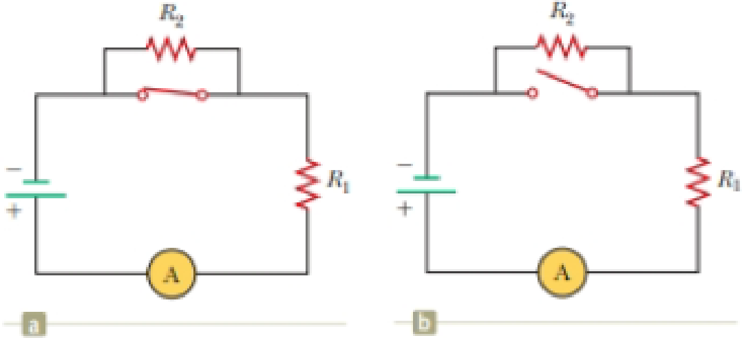
With the switch in the circuit of Figure 27.4a closed, there is no current in R2 because the current has an alternate zero-resistance path through the switch. There is current in R1, and this current is measured with the ammeter (a device for measuring current) at the bottom of the circuit. If the switch is opened (Fig. 27.4b), there is current in R2. What happens to the reading on the ammeter when the switch is opened? (a) The reading goes up. (b) The reading goes down. (c) The reading does not change.
Figure 27.4 (Quick Quiz 27.2) What happens when the switch is opened?

Trending nowThis is a popular solution!

Chapter 27 Solutions
Physics for Scientists and Engineers with Modern Physics
Additional Science Textbook Solutions
Chemistry: The Central Science (14th Edition)
Human Biology: Concepts and Current Issues (8th Edition)
Campbell Biology (11th Edition)
Cosmic Perspective Fundamentals
Human Physiology: An Integrated Approach (8th Edition)
- Your RL circuit has a characteristic time constant of 19.5 ns, and a resistance of 4.60 MQ. (a) What is the inductance (in H) of the circuit? H (b) What resistance (in MQ) should you use (instead of the 4.60 MQ resistor) to obtain a 1.00 ns time constant, perhaps needed for quick response in an oscilloscope? ΜΩarrow_forwardAt a distance of 0.212 cm from the center of a charged conducting sphere with radius 0.100cm, the electric field is 485 N/C . What is the electric field 0.598 cm from the center of the sphere? At a distance of 0.196 cmcm from the axis of a very long charged conducting cylinder with radius 0.100cm, the electric field is 485 N/C . What is the electric field 0.620 cm from the axis of the cylinder? At a distance of 0.202 cm from a large uniform sheet of charge, the electric field is 485 N/C . What is the electric field 1.21 cm from the sheet?arrow_forwardA hollow, conducting sphere with an outer radius of 0.260 m and an inner radius of 0.200 m has a uniform surface charge density of +6.67 × 10⁻⁶ C/m2. A charge of -0.800 μC is now introduced into the cavity inside the sphere. What is the new charge density on the outside of the sphere? Calculate the strength of the electric field just outside the sphere. What is the electric flux through a spherical surface just inside the inner surface of the sphere?arrow_forward
- A point charge of -3.00 μC is located in the center of a spherical cavity of radius 6.60 cm inside an insulating spherical charged solid. The charge density in the solid is 7.35 × 10⁻⁴ C/m3. Calculate the magnitude of the electric field inside the solid at a distance of 9.10 cm from the center of the cavity. Find the direction of this electric field.arrow_forwardAn infinitely long conducting cylindrical rod with a positive charge λ per unit length is surrounded by a conducting cylindrical shell (which is also infinitely long) with a charge per unit length of −2λ and radius r1, as shown in the figure. What is E(r), the radial component of the electric field between the rod and cylindrical shell as a function of the distance r from the axis of the cylindrical rod? Express your answer in terms of λ, r, and ϵ0, the permittivity of free space. What is σinner, the surface charge density (charge per unit area) on the inner surface of the conducting shell? What is σouterσouter, the surface charge density on the outside of the conducting shell? (Recall from the problem statement that the conducting shell has a total charge per unit length given by −2λ.) What is the radial component of the electric field, E(r), outside the shell?arrow_forwardA very long conducting tube (hollow cylinder) has inner radius aa and outer radius b. It carries charge per unit length +α, where αα is a positive constant with units of C/m. A line of charge lies along the axis of the tube. The line of charge has charge per unit length +α. Calculate the electric field in terms of α and the distance r from the axis of the tube for r<a. Calculate the electric field in terms of α and the distance rr from the axis of the tube for a<r<b. Calculate the electric field in terms of αα and the distance r from the axis of the tube for r>b. What is the charge per unit length on the inner surface of the tube? What is the charge per unit length on the outer surface of the tube?arrow_forward
- Two small insulating spheres with radius 9.00×10⁻² m are separated by a large center-to-center distance of 0.545 m . One sphere is negatively charged, with net charge -1.75 μC , and the other sphere is positively charged, with net charge 3.70 μC . The charge is uniformly distributed within the volume of each sphere. What is the magnitude E of the electric field midway between the spheres? Take the permittivity of free space to be ϵ0 = 8.85×10⁻¹² C2/(N⋅m2) . What is the direction of the electric field midway between the spheres?arrow_forwardA conducting spherical shell with inner radius aa and outer radius bb has a positive point charge Q located at its center. The total charge on the shell is -3Q, and it is insulated from its surroundings. Derive the expression for the electric field magnitude in terms of the distance r from the center for the region r<a. Express your answer in terms of some or all of the variables Q, a, b, and appropriate constants. Derive the expression for the electric field magnitude in terms of the distance rr from the center for the region a<r<b. Derive the expression for the electric field magnitude in terms of the distance rr from the center for the region r>b. What is the surface charge density on the inner surface of the conducting shell? What is the surface charge density on the outer surface of the conducting shell?arrow_forwardA small sphere with a mass of 3.00×10⁻³ g and carrying a charge of 4.80×10⁻⁸ C hangs from a thread near a very large, charged insulating sheet, as shown in the figure (Figure 1). The charge density on the sheet is −2.20×10⁻⁹ C/m2 . Find the angle of the thread.arrow_forward
- A small conducting spherical shell with inner radius aa and outer radius bb is concentric with a larger conducting spherical shell with inner radius c and outer radius d (Figure 1). The inner shell has total charge +2q, and the outer shell has charge −2q. Calculate the magnitude of the electric field in terms of q and the distance rr from the common center of the two shells for r<a. Calculate the magnitude of the electric field for a<r<b. Calculate the magnitude of the electric field for b<r<c.arrow_forwardA cube has sides of length L = 0.800 m . It is placed with one corner at the origin as shown in the figure. The electric field is not uniform but is given by E→=αxi^+βzk^, where α=−3.90 and β= 7.10. What is the sum of the flux through the surface S5 and S6? What is the sum of the flux through the surface S2 and S4? Find the total electric charge inside the cube.arrow_forwardIn the figure, a proton is projected horizontally midway between two parallel plates that are separated by 0.6 cm. The electrical field due to the plates has magnitude 450000 N/C between the plates away from the edges. If the plates are 3 cm long, find the minimum speed of the proton if it just misses the lower plate as it emerges from the field.arrow_forward
 Physics for Scientists and Engineers with Modern ...PhysicsISBN:9781337553292Author:Raymond A. Serway, John W. JewettPublisher:Cengage Learning
 Physics for Scientists and EngineersPhysicsISBN:9781337553278Author:Raymond A. Serway, John W. JewettPublisher:Cengage Learning
 Physics for Scientists and Engineers, Technology ...PhysicsISBN:9781305116399Author:Raymond A. Serway, John W. JewettPublisher:Cengage Learning
 College PhysicsPhysicsISBN:9781938168000Author:Paul Peter Urone, Roger HinrichsPublisher:OpenStax College
 Principles of Physics: A Calculus-Based TextPhysicsISBN:9781133104261Author:Raymond A. Serway, John W. JewettPublisher:Cengage Learning
 Physics for Scientists and Engineers: Foundations...PhysicsISBN:9781133939146Author:Katz, Debora M.Publisher:Cengage Learning


