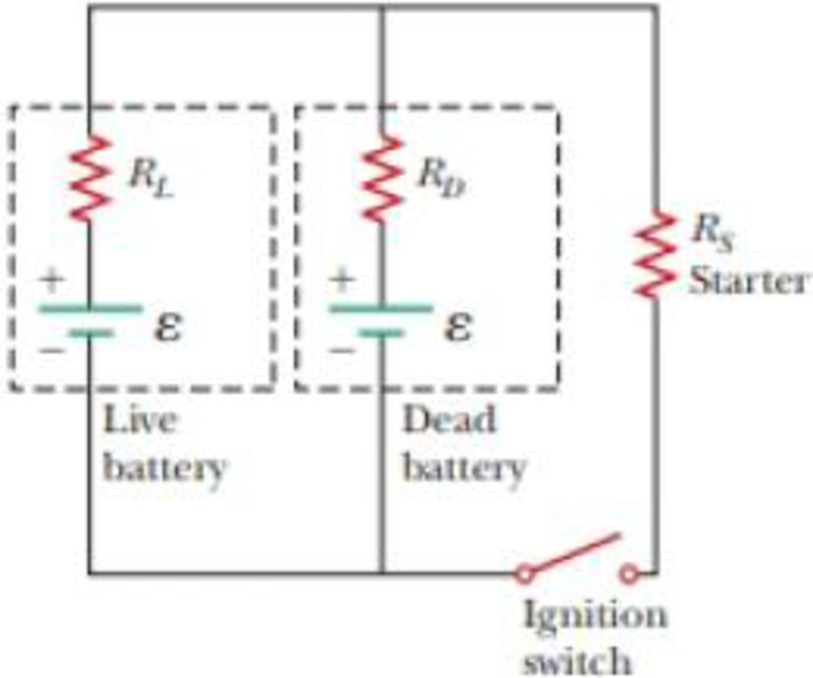
You have a faculty position at a community college and are teaching a class in automotive technology. You are deep in a discussion of using jumper cables to start a car with a dead battery from a car with a fresh battery. You have drawn the circuit diagram in Figure P27.16 to explain the process. The battery on the left is the live battery in the correctly functioning car, with emf ε and internal resistance RL, where the L subscript refers to “live.” Its terminals are connected directly across those of the dead battery, in the middle of the diagram, with emf ε and internal resistance RD, where the D subscript refers to “dead.” Then, the starter in the car with the dead battery is activated by closing the ignition switch, allowing the car to start. The resistance of the starter is RS. A student raises his hand and asks, “So is the dead battery being charged while the starter is operating?” How do you respond?
Figure P27.16

Trending nowThis is a popular solution!

Chapter 27 Solutions
Physics for Scientists and Engineers with Modern Physics
Additional Science Textbook Solutions
Fundamentals of Anatomy & Physiology (11th Edition)
Laboratory Manual For Human Anatomy & Physiology
General, Organic, and Biological Chemistry - 4th edition
Microbiology Fundamentals: A Clinical Approach
Chemistry: A Molecular Approach (4th Edition)
Introductory Chemistry (6th Edition)
- 2. List three places besides in springs where Hooke's law applies.arrow_forward1. What is the spring constant of a spring that starts 10.0 cm long and extends to 11.4 cm with a 300 g mass hanging from it?arrow_forwardplease help me solve all parts of this question from physics. thanks so much in advance! :)))arrow_forward
- A fluid with density 263 kg/m3 flows through a pipe of varying diameter and height. At location 1 the flow speed is 13.5 m/s and the diameter of the pipe is 7.4 cm down to location 2 the pipe diameter is 16.9 cm. Location 1 is 6.3 meters higher than location 2. What is the difference in pressure P2 - P1? Using units in Pascals and use g = 9.81 m/s2.arrow_forwardThe kitchen had a temperature 46 degrees Fahrenheit and was converted it to Kelvin. What is the correct number for this temperature (46 F) on the Kelvin scale?arrow_forwardWater is traveling at a speed of 0.65 m/s through a pipe with a cross-section radius of 0.23 meters. The water enters a section of pipe that has a smaller radius, only 0.11 meters. What is the speed of the water traveling in this narrower section of pipe?arrow_forward
- A particular water pipe has a radius of 0.28 meters. If the pipe is completely filled with water, moving with average velocity 0.45 m/s, what is the flow rate of water through the pipe with units of cubic meters of water per second?arrow_forwardWater is flowing through a horizontal pipe with two segments. In one segment, the water flows at a speed v1 = 4.52 m/s. In the second segment the speed of the water is v2 = 2.38 m/s. Based on Bernoulli's Principle, what is the difference in pressure (P2 - P1) between the two segments? Assume that the density of the water is 997 kg/m3 and give your answer as the number of Pascals (i.e. N/m2).arrow_forwardWater from the faucet is supplied to the hose at a rate of 0.00057 m3/s. At what speed (number of meters per second) does the water exit the nozzle if the cross sectional area of the narrow nozzle is 2.1 x 10⁻⁶ m2?arrow_forward
- Jason Fruits/Indiana University Research Communications Silver/ silver oxide Zinc zinc/oxidearrow_forwardCar P moves to the west with constant speed v0 along a straight road. Car Q starts from rest at instant 1, and moves to the west with increasing speed. At instant 5, car Q has speed w0 relative to the road (w0 < v0). Instants 1-5 are separated by equal time intervals. At instant 3, cars P and Q are adjacent to one another (i.e., they have the same position). In the reference frame o f the road, at instant 3 i s the speed o f car Q greater than, less than, or equal to the speed of car P? Explain.arrow_forwardCar P moves to the west with constant speed v0 along a straight road. Car Q starts from rest at instant 1, and moves to the west with increasing speed. At instant 5, car Q has speed w0 relative to the road (w0 < v0). Instants 1-5 are separated by equal time intervals.arrow_forward
 Principles of Physics: A Calculus-Based TextPhysicsISBN:9781133104261Author:Raymond A. Serway, John W. JewettPublisher:Cengage Learning
 Physics for Scientists and Engineers: Foundations...PhysicsISBN:9781133939146Author:Katz, Debora M.Publisher:Cengage Learning
 College PhysicsPhysicsISBN:9781938168000Author:Paul Peter Urone, Roger HinrichsPublisher:OpenStax College
 Physics for Scientists and EngineersPhysicsISBN:9781337553278Author:Raymond A. Serway, John W. JewettPublisher:Cengage Learning
 Physics for Scientists and Engineers with Modern ...PhysicsISBN:9781337553292Author:Raymond A. Serway, John W. JewettPublisher:Cengage Learning


