
Engineering Mechanics: Statics
8th Edition
ISBN: 9781118807330
Author: James L. Meriam, L. G. Kraige, J. N. Bolton
Publisher: WILEY
expand_more
expand_more
format_list_bulleted
Videos
Textbook Question
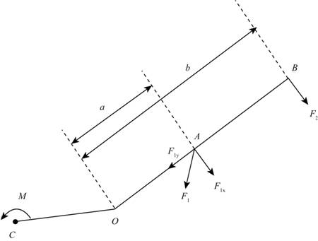
Chapter 2.6, Problem 87P
If the resultant of the two forces and couple M passes through point O, determine M.
Expert Solution & Answer
Want to see the full answer?
Check out a sample textbook solution
Students have asked these similar questions
PROBLEM 3.23
3.23 Under normal operating condi-
tions a motor exerts a torque of
magnitude TF at F. The shafts
are made of a steel for which
the allowable shearing stress is
82 MPa and have diameters of
dCDE=24 mm and dFGH = 20
mm. Knowing that rp = 165
mm and rg114 mm, deter-
mine the largest torque TF
which may be exerted at F.
TF
F
rG-
rp
B
CH
TE
E
1. (16%) (a) If a ductile material fails under pure torsion, please explain the failure
mode and describe the observed plane of failure.
(b) Suppose a prismatic beam is subjected to equal and opposite couples as shown
in Fig. 1. Please sketch the deformation and the stress distribution of the cross
section.
M
M
Fig. 1
(c) Describe the definition of the neutral axis.
(d) Describe the definition of the modular ratio.
using the theorem of three moments, find all the moments, I only need concise calculations with minimal explanations. The correct answers are provided at the bottom
Chapter 2 Solutions
Engineering Mechanics: Statics
Ch. 2.3 - The force F has a magnitude of 800 N. Express F as...Ch. 2.3 - The force F has a magnitude of 7 kN and acts at...Ch. 2.3 - The slope of the 6.5-kN force F is specified as...Ch. 2.3 - The force F has a magnitude of 1250 lb and has the...Ch. 2.3 - The control rod AP exerts a force F on the sector...Ch. 2.3 - Two forces are applied to the construction bracket...Ch. 2.3 - Two individuals are attempting to relocate a sofa...Ch. 2.3 - A small probe P is gently forced against the...Ch. 2.3 - The y-component of the force F which a person...Ch. 2.3 - Determine the x-y and n-t components of the 13-kip...
Ch. 2.3 - The two structural members, one of which is in...Ch. 2.3 - The guy cables AB and AC are attached to the top...Ch. 2.3 - If the equal tensions T in the pulley cable are...Ch. 2.3 - Two people exert the forces shown on the potted...Ch. 2.3 - A compressive force F is transmitted via the...Ch. 2.3 - A force F of magnitude 800 lb is applied to point...Ch. 2.3 - The two forces shown act in the x-y plane of the...Ch. 2.3 - Determine the x- and y-components of the tension T...Ch. 2.3 - Refer to the mechanism of the previous problem....Ch. 2.3 - Determine the magnitude Fs of the tensile spring...Ch. 2.3 - Determine the resultant R of the two forces...Ch. 2.3 - A sheet of an experimental composite is subjected...Ch. 2.3 - Determine the scalar components Ra and Rb of the...Ch. 2.3 - Determine the components Fa and Fb of the 4-kN...Ch. 2.3 - If the projection Pa and component Fb of the force...Ch. 2.3 - It is desired to remove the spike from the timber...Ch. 2.3 - At what angle must the 800-lb force be applied in...Ch. 2.3 - Power is to be transferred from the pinion A to...Ch. 2.3 - To insert the small cylindrical part into a...Ch. 2.3 - The unstretched length of the spring is r. When...Ch. 2.4 - Determine the moments of the 5-kN force about...Ch. 2.4 - The force of magnitude F acts along the edge of...Ch. 2.4 - The rectangular plate is made up of 1-ft squares...Ch. 2.4 - Calculate the moment of the 250-N force on the...Ch. 2.4 - An experimental device imparts a force of...Ch. 2.4 - A force F of magnitude 60 N is applied to the...Ch. 2.4 - A man uses a crowbar to lift the corner of a hot...Ch. 2.4 - An overhead view of a door is shown. If the...Ch. 2.4 - The 30-N force P is applied perpendicular to the...Ch. 2.4 - A man exerts a force F on the handle of the...Ch. 2.4 - A 32-lb pull T is applied to a cord, which is...Ch. 2.4 - As a trailer is towed in the forward direction,...Ch. 2.4 - Determine the general expressions for the moments...Ch. 2.4 - The mechanism of Prob. 2/15 is repeated here....Ch. 2.4 - Determine the moments of the tension T about point...Ch. 2.4 - In raising the pole from the position shown, the...Ch. 2.4 - The lower lumbar region A of the spine is the part...Ch. 2.4 - A gate is held in the position shown by cable AB....Ch. 2.4 - In order to raise the flagpole OC, a light frame...Ch. 2.4 - Elements of the lower arm are shown in the figure....Ch. 2.4 - As the result of a wind blowing normal to the...Ch. 2.4 - The masthead fitting supports the two forces...Ch. 2.4 - The small crane is mounted along the side of a...Ch. 2.4 - The 120-N force is applied as shown to one end of...Ch. 2.4 - The bent cantilever beam is acted upon by an 8-kN...Ch. 2.4 - The mechanism shown is used to lower disabled...Ch. 2.4 - The asymmetrical support arrangement is chosen for...Ch. 2.4 - The woman maintains a slow steady motion over the...Ch. 2.5 - The caster unit is subjected to the pair of 80-lb...Ch. 2.5 - For F=65lb, compute the combined moment of the two...Ch. 2.5 - The indicated force—couple system is applied to...Ch. 2.5 - Replace the 3.2-kN force by an equivalent...Ch. 2.5 - As part of a test, the two aircraft engines are...Ch. 2.5 - The cantilevered W530150 beam shown is subjected...Ch. 2.5 - Each propeller of the twin-screw ship develops a...Ch. 2.5 - The upper hinge A of the uniform cabinet door has...Ch. 2.5 - A lug wrench is used to tighten a square-head...Ch. 2.5 - The force F is applied at the end of arm ACD,...Ch. 2.5 - A force F of magnitude 50 N is exerted on the...Ch. 2.5 - An overhead view of a portion of an exercise...Ch. 2.5 - The tie-rod AB exerts the 250-N force on the...Ch. 2.5 - The 20-N force F is applied to the handle of the...Ch. 2.5 - An overhead view of the handlebars on an...Ch. 2.5 - The force F is applied to the leg-extension...Ch. 2.5 - The system consisting of the bar OA, two identical...Ch. 2.5 - The device shown is a part of an automobile seat-...Ch. 2.5 - Replace the two cable tensions which act on the...Ch. 2.5 - The force F acts along line MA, where M is the...Ch. 2.6 - Determine the resultant R of the three tension...Ch. 2.6 - Determine the force magnitude F and direction ...Ch. 2.6 - Replace the three horizontal forces and applied...Ch. 2.6 - Determine the equivalent force-couple system at...Ch. 2.6 - Determine the equivalent force-couple system at O...Ch. 2.6 - Determine the height h above the base B at which...Ch. 2.6 - Where does the resultant of the two forces act?Ch. 2.6 - If the resultant of the loads shown passes through...Ch. 2.6 - If the resultant of the two forces and couple M...Ch. 2.6 - If the resultant of the forces shown passes...Ch. 2.6 - Replace the three forces acting on the bent pipe...Ch. 2.6 - Four people are attempting to move a stage...Ch. 2.6 - Replace the three forces which act on the bent bar...Ch. 2.6 - Uneven terrain conditions cause the left front...Ch. 2.6 - A commercial airliner with four jet engines, each...Ch. 2.6 - Determine the x- and y-axis intercepts of the line...Ch. 2.6 - Replace the three cable tensions acting on the...Ch. 2.6 - Determine the resultant R of the three forces...Ch. 2.6 - For the truss loaded as shown, determine the...Ch. 2.6 - Five forces are applied to the beam trolley as...Ch. 2.6 - As part of a design test, the camshaft-drive...Ch. 2.6 - An exhaust system for a pickup truck is shown in...Ch. 2.7 - Express F as a vector in terms of the unit vectors...Ch. 2.7 - Cable AB exerts a force of magnitude F=6kN on...Ch. 2.7 - Express the 5-kN force F as a vector in terms of...Ch. 2.7 - The force F has a magnitude of 300 1b and acts...Ch. 2.7 - If the tension in the gantry-crane hoisting cable...Ch. 2.7 - The turnbuckle is tightened until the tension in...Ch. 2.7 - If the tension in cable AB is 1750 lb, determine...Ch. 2.7 - The tension in the supporting cable AB is T=425N....Ch. 2.7 - The force F has a magnitude of 2 kN and is...Ch. 2.7 - The tension in the supporting cable AB is 10 kN....Ch. 2.7 - If the tension in cable CD is T=675lb, determine...Ch. 2.7 - If the tension in cable DE is T=575N, determine...Ch. 2.7 - Determine the angle between the 200-lb force and...Ch. 2.7 - Compression member AB is used to hold up the...Ch. 2.7 - Determine a general expression for the scalar...Ch. 2.7 - If the scalar projection of F onto line OA is O,...Ch. 2.7 - The rectangular plate is supported by hinges along...Ch. 2.7 - Express the force F in terms of the unit vectors...Ch. 2.7 - A force F is applied to the surface of the sphere...Ch. 2.7 - Determine the x-, y-, and z-components of force F...Ch. 2.8 - Determine the moment of force F about point O.Ch. 2.8 - Determine the moment of force F about point A.Ch. 2.8 - Determine the moment about O of the force of...Ch. 2.8 - The 4-lb force is applied at point A of the crank...Ch. 2.8 - The steel H-beam is being designed as a column to...Ch. 2.8 - Determine the moment associated with the pair of...Ch. 2.8 - The turnbuckle is tightened until the tension in...Ch. 2.8 - The system of Prob. 2/111 is repeated here, and...Ch. 2.8 - The two forces acting on the handles of the pipe...Ch. 2.8 - The gantry crane of Prob. 2/105 is repeated here,...Ch. 2.8 - Determine the combined moment made by the two...Ch. 2.8 - A helicopter is shown here with certain...Ch. 2.8 - The system of Prob. 2/108 is repeated here, and...Ch. 2.8 - The structure shown is constructed of circular rod...Ch. 2.8 - Two 1.2-lb thrusters on the nonrotating satellite...Ch. 2.8 - If the tension in cable DE is 575 N, determine the...Ch. 2.8 - Determine the moment of each individual force...Ch. 2.8 - The system of Prob. 2/107 is repeated here, and...Ch. 2.8 - A space shuttle orbiter is subjected to thrusts...Ch. 2.8 - The specialty wrench shown in the figure is...Ch. 2.8 - The 75-N force acts perpendicular to the bent...Ch. 2.8 - The body is composed of a slender uniform rod bent...Ch. 2.8 - If F1=450N and the magnitude of the moment of both...Ch. 2.8 - A 1.8-lb vertical force is applied to the knob of...Ch. 2.8 - A basketball player applies a force F=65lb to the...Ch. 2.8 - The special-purpose milling cutter is subjected to...Ch. 2.8 - The force F acts along an element of the right...Ch. 2.8 - The spring of k and unstretched length 1.5R is...Ch. 2.9 - Three forces act at point O. If it is known that...Ch. 2.9 - Three equal forces are exerted on the equilateral...Ch. 2.9 - The thin rectangular plate is subjected to the...Ch. 2.9 - An oil tanker moves away from its docked position...Ch. 2.9 - Determine the x- and y-coordinates of a point...Ch. 2.9 - The two forces and one couple act on the elements...Ch. 2.9 - Represent the resultant of the force system acting...Ch. 2.9 - Determine the force-couple system at O which is...Ch. 2.9 - The portion of a bridge truss is subjected to...Ch. 2.9 - The pulley and gear are subjected to the loads...Ch. 2.9 - The commercial airliner of Prob. 2/93 is redrawn...Ch. 2.9 - Replace the three forces acting on the rectangular...Ch. 2.9 - While cutting a piece of paper, a person exerts...Ch. 2.9 - The floor exerts the four indicated forces on the...Ch. 2.9 - Replace the three forces acting on the structural...Ch. 2.9 - Replace the two forces and one couple acting on...Ch. 2.9 - Replace the two forces acting on the pole by a...Ch. 2.9 - For the system of Prob. 2154, write the moment M...Ch. 2.9 - Replace the two forces which act on the...Ch. 2.9 - For the system of forces in Prob. 2/167, determine...Ch. 2.10 - Using the principles of equilibrium to be...Ch. 2.10 - The three forces act perpendicular to the...Ch. 2.10 - A die is being used to cut threads on a rod. If...Ch. 2.10 - The blades of the portable fan generate a 1.2-lb...Ch. 2.10 - Determine the moment of the force P about point A.Ch. 2.10 - The directions of rotation of the input shaft A...Ch. 2.10 - The control lever is subjected to a clockwise...Ch. 2.10 - For the angular position =60 of the crank OA, the...Ch. 2.10 - Calculate the moment MO of the 250-N force about...Ch. 2.10 - During a drilling operation, the small robotic...Ch. 2.10 - Reduce the given loading system to a force-couple...Ch. 2.10 - The 300500700-mm column is subjected to the...Ch. 2.10 - When the pole OA is in the position shown, the...Ch. 2.10 - The combined action of the three forces on the...Ch. 2.10 - Four forces are exerted on the eyebolt as shown....Ch. 2.10 - The force F is directed from A toward D and D is...Ch. 2.10 - With the 300-lb cylindrical part P in its grip,...Ch. 2.10 - A flagpole with attached light triangular frame is...Ch. 2.10 - Plot the magnitude of the resultant R of the three...Ch. 2.10 - For the previous problem, determine the...Ch. 2.10 - The throttle-control lever OA rotates in the range...Ch. 2.10 - For the rectangular parallelepiped shown, develop...Ch. 2.10 - Consider the rectangular parallelepiped of Prob....Ch. 2.10 - A motor attached to the shaft at O causes the arm...
Additional Engineering Textbook Solutions
Find more solutions based on key concepts
Why is it useful for a programmer to have some background in language design, even though he or she may never a...
Concepts Of Programming Languages
Using Vole machine language (Appendix C), write a program that places a 1 in the most significant bit of the me...
Computer Science: An Overview (13th Edition) (What's New in Computer Science)
In Exercises 49 through 54, find the value of the given function. Math.Round(2.6)
Introduction To Programming Using Visual Basic (11th Edition)
For the circuit shown, find (a) the voltage υ, (b) the power delivered to the circuit by the current source, an...
Electric Circuits. (11th Edition)
Explain forward-only cursors. Give an example of their use.
Database Concepts (8th Edition)
ofstream file; file.open (info.dat, ios::tin); if (file) { cout Could not open file.\n; }
Starting Out with C++ from Control Structures to Objects (9th Edition)
Knowledge Booster


Learn more about
Need a deep-dive on the concept behind this application? Look no further. Learn more about this topic, mechanical-engineering and related others by exploring similar questions and additional content below.Similar questions
- PROBLEM 3.46 The solid cylindrical rod BC of length L = 600 mm is attached to the rigid lever AB of length a = 380 mm and to the support at C. When a 500 N force P is applied at A, design specifications require that the displacement of A not exceed 25 mm when a 500 N force P is applied at A For the material indicated determine the required diameter of the rod. Aluminium: Tall = 65 MPa, G = 27 GPa. Aarrow_forwardFind the equivalent mass of the rocker arm assembly with respect to the x coordinate. k₁ mi m2 k₁arrow_forward2. Figure below shows a U-tube manometer open at both ends and containing a column of liquid mercury of length l and specific weight y. Considering a small displacement x of the manometer meniscus from its equilibrium position (or datum), determine the equivalent spring constant associated with the restoring force. Datum Area, Aarrow_forward
- 1. The consequences of a head-on collision of two automobiles can be studied by considering the impact of the automobile on a barrier, as shown in figure below. Construct a mathematical model (i.e., draw the diagram) by considering the masses of the automobile body, engine, transmission, and suspension and the elasticity of the bumpers, radiator, sheet metal body, driveline, and engine mounts.arrow_forward3.) 15.40 – Collar B moves up at constant velocity vB = 1.5 m/s. Rod AB has length = 1.2 m. The incline is at angle = 25°. Compute an expression for the angular velocity of rod AB, ė and the velocity of end A of the rod (✓✓) as a function of v₂,1,0,0. Then compute numerical answers for ȧ & y_ with 0 = 50°.arrow_forward2.) 15.12 The assembly shown consists of the straight rod ABC which passes through and is welded to the grectangular plate DEFH. The assembly rotates about the axis AC with a constant angular velocity of 9 rad/s. Knowing that the motion when viewed from C is counterclockwise, determine the velocity and acceleration of corner F.arrow_forward
arrow_back_ios
SEE MORE QUESTIONS
arrow_forward_ios
Recommended textbooks for you
 International Edition---engineering Mechanics: St...Mechanical EngineeringISBN:9781305501607Author:Andrew Pytel And Jaan KiusalaasPublisher:CENGAGE L
International Edition---engineering Mechanics: St...
Mechanical Engineering
ISBN:9781305501607
Author:Andrew Pytel And Jaan Kiusalaas
Publisher:CENGAGE L
How to balance a see saw using moments example problem; Author: Engineer4Free;https://www.youtube.com/watch?v=d7tX37j-iHU;License: Standard Youtube License