
Engineering Mechanics: Statics
8th Edition
ISBN: 9781118807330
Author: James L. Meriam, L. G. Kraige, J. N. Bolton
Publisher: WILEY
expand_more
expand_more
format_list_bulleted
Concept explainers
Videos
Textbook Question
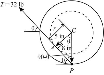
Chapter 2.4, Problem 41P
A 32-lb pull T is applied to a cord, which is wound securely around the inner hub of the drum. Determine the moment of T about the drum center C. At what angle
Expert Solution & Answer
Want to see the full answer?
Check out a sample textbook solution
Students have asked these similar questions
Qu 1 If crank OA rotates with an angular velocity of ω = 12 rad/s, determine the velocity of piston B and
the angular velocity of rod AB at the instant shown.
please show all work
Q2/ Maria has an online shop where she sells hand made paintings and
cards. She sells the painting for 50 and the card for 20. It takes her 2 hours
to complete 1 painting and 45 minutes to make a single card. She also has
a day job and makes paintings and cards in her free time. She cannot spend
more than 15 hours a week to make paintings and cards. Additionally, she
should make not more than 10 paintings and cards per week.
She makes a profit of 25 on painting and 15 on each card. How many
paintings and cards should she make each week to maximize her profit.
For the beam and loading shown, (a) draw the shear and bending moment diagrams, (b) determine the magnitude and location of the maximum absolute value of the bending momentConsider A = 0please show step by step process, i did something wrong with bending moment diagram( length of beam = 2 + 6 + 2)
Chapter 2 Solutions
Engineering Mechanics: Statics
Ch. 2.3 - The force F has a magnitude of 800 N. Express F as...Ch. 2.3 - The force F has a magnitude of 7 kN and acts at...Ch. 2.3 - The slope of the 6.5-kN force F is specified as...Ch. 2.3 - The force F has a magnitude of 1250 lb and has the...Ch. 2.3 - The control rod AP exerts a force F on the sector...Ch. 2.3 - Two forces are applied to the construction bracket...Ch. 2.3 - Two individuals are attempting to relocate a sofa...Ch. 2.3 - A small probe P is gently forced against the...Ch. 2.3 - The y-component of the force F which a person...Ch. 2.3 - Determine the x-y and n-t components of the 13-kip...
Ch. 2.3 - The two structural members, one of which is in...Ch. 2.3 - The guy cables AB and AC are attached to the top...Ch. 2.3 - If the equal tensions T in the pulley cable are...Ch. 2.3 - Two people exert the forces shown on the potted...Ch. 2.3 - A compressive force F is transmitted via the...Ch. 2.3 - A force F of magnitude 800 lb is applied to point...Ch. 2.3 - The two forces shown act in the x-y plane of the...Ch. 2.3 - Determine the x- and y-components of the tension T...Ch. 2.3 - Refer to the mechanism of the previous problem....Ch. 2.3 - Determine the magnitude Fs of the tensile spring...Ch. 2.3 - Determine the resultant R of the two forces...Ch. 2.3 - A sheet of an experimental composite is subjected...Ch. 2.3 - Determine the scalar components Ra and Rb of the...Ch. 2.3 - Determine the components Fa and Fb of the 4-kN...Ch. 2.3 - If the projection Pa and component Fb of the force...Ch. 2.3 - It is desired to remove the spike from the timber...Ch. 2.3 - At what angle must the 800-lb force be applied in...Ch. 2.3 - Power is to be transferred from the pinion A to...Ch. 2.3 - To insert the small cylindrical part into a...Ch. 2.3 - The unstretched length of the spring is r. When...Ch. 2.4 - Determine the moments of the 5-kN force about...Ch. 2.4 - The force of magnitude F acts along the edge of...Ch. 2.4 - The rectangular plate is made up of 1-ft squares...Ch. 2.4 - Calculate the moment of the 250-N force on the...Ch. 2.4 - An experimental device imparts a force of...Ch. 2.4 - A force F of magnitude 60 N is applied to the...Ch. 2.4 - A man uses a crowbar to lift the corner of a hot...Ch. 2.4 - An overhead view of a door is shown. If the...Ch. 2.4 - The 30-N force P is applied perpendicular to the...Ch. 2.4 - A man exerts a force F on the handle of the...Ch. 2.4 - A 32-lb pull T is applied to a cord, which is...Ch. 2.4 - As a trailer is towed in the forward direction,...Ch. 2.4 - Determine the general expressions for the moments...Ch. 2.4 - The mechanism of Prob. 2/15 is repeated here....Ch. 2.4 - Determine the moments of the tension T about point...Ch. 2.4 - In raising the pole from the position shown, the...Ch. 2.4 - The lower lumbar region A of the spine is the part...Ch. 2.4 - A gate is held in the position shown by cable AB....Ch. 2.4 - In order to raise the flagpole OC, a light frame...Ch. 2.4 - Elements of the lower arm are shown in the figure....Ch. 2.4 - As the result of a wind blowing normal to the...Ch. 2.4 - The masthead fitting supports the two forces...Ch. 2.4 - The small crane is mounted along the side of a...Ch. 2.4 - The 120-N force is applied as shown to one end of...Ch. 2.4 - The bent cantilever beam is acted upon by an 8-kN...Ch. 2.4 - The mechanism shown is used to lower disabled...Ch. 2.4 - The asymmetrical support arrangement is chosen for...Ch. 2.4 - The woman maintains a slow steady motion over the...Ch. 2.5 - The caster unit is subjected to the pair of 80-lb...Ch. 2.5 - For F=65lb, compute the combined moment of the two...Ch. 2.5 - The indicated force—couple system is applied to...Ch. 2.5 - Replace the 3.2-kN force by an equivalent...Ch. 2.5 - As part of a test, the two aircraft engines are...Ch. 2.5 - The cantilevered W530150 beam shown is subjected...Ch. 2.5 - Each propeller of the twin-screw ship develops a...Ch. 2.5 - The upper hinge A of the uniform cabinet door has...Ch. 2.5 - A lug wrench is used to tighten a square-head...Ch. 2.5 - The force F is applied at the end of arm ACD,...Ch. 2.5 - A force F of magnitude 50 N is exerted on the...Ch. 2.5 - An overhead view of a portion of an exercise...Ch. 2.5 - The tie-rod AB exerts the 250-N force on the...Ch. 2.5 - The 20-N force F is applied to the handle of the...Ch. 2.5 - An overhead view of the handlebars on an...Ch. 2.5 - The force F is applied to the leg-extension...Ch. 2.5 - The system consisting of the bar OA, two identical...Ch. 2.5 - The device shown is a part of an automobile seat-...Ch. 2.5 - Replace the two cable tensions which act on the...Ch. 2.5 - The force F acts along line MA, where M is the...Ch. 2.6 - Determine the resultant R of the three tension...Ch. 2.6 - Determine the force magnitude F and direction ...Ch. 2.6 - Replace the three horizontal forces and applied...Ch. 2.6 - Determine the equivalent force-couple system at...Ch. 2.6 - Determine the equivalent force-couple system at O...Ch. 2.6 - Determine the height h above the base B at which...Ch. 2.6 - Where does the resultant of the two forces act?Ch. 2.6 - If the resultant of the loads shown passes through...Ch. 2.6 - If the resultant of the two forces and couple M...Ch. 2.6 - If the resultant of the forces shown passes...Ch. 2.6 - Replace the three forces acting on the bent pipe...Ch. 2.6 - Four people are attempting to move a stage...Ch. 2.6 - Replace the three forces which act on the bent bar...Ch. 2.6 - Uneven terrain conditions cause the left front...Ch. 2.6 - A commercial airliner with four jet engines, each...Ch. 2.6 - Determine the x- and y-axis intercepts of the line...Ch. 2.6 - Replace the three cable tensions acting on the...Ch. 2.6 - Determine the resultant R of the three forces...Ch. 2.6 - For the truss loaded as shown, determine the...Ch. 2.6 - Five forces are applied to the beam trolley as...Ch. 2.6 - As part of a design test, the camshaft-drive...Ch. 2.6 - An exhaust system for a pickup truck is shown in...Ch. 2.7 - Express F as a vector in terms of the unit vectors...Ch. 2.7 - Cable AB exerts a force of magnitude F=6kN on...Ch. 2.7 - Express the 5-kN force F as a vector in terms of...Ch. 2.7 - The force F has a magnitude of 300 1b and acts...Ch. 2.7 - If the tension in the gantry-crane hoisting cable...Ch. 2.7 - The turnbuckle is tightened until the tension in...Ch. 2.7 - If the tension in cable AB is 1750 lb, determine...Ch. 2.7 - The tension in the supporting cable AB is T=425N....Ch. 2.7 - The force F has a magnitude of 2 kN and is...Ch. 2.7 - The tension in the supporting cable AB is 10 kN....Ch. 2.7 - If the tension in cable CD is T=675lb, determine...Ch. 2.7 - If the tension in cable DE is T=575N, determine...Ch. 2.7 - Determine the angle between the 200-lb force and...Ch. 2.7 - Compression member AB is used to hold up the...Ch. 2.7 - Determine a general expression for the scalar...Ch. 2.7 - If the scalar projection of F onto line OA is O,...Ch. 2.7 - The rectangular plate is supported by hinges along...Ch. 2.7 - Express the force F in terms of the unit vectors...Ch. 2.7 - A force F is applied to the surface of the sphere...Ch. 2.7 - Determine the x-, y-, and z-components of force F...Ch. 2.8 - Determine the moment of force F about point O.Ch. 2.8 - Determine the moment of force F about point A.Ch. 2.8 - Determine the moment about O of the force of...Ch. 2.8 - The 4-lb force is applied at point A of the crank...Ch. 2.8 - The steel H-beam is being designed as a column to...Ch. 2.8 - Determine the moment associated with the pair of...Ch. 2.8 - The turnbuckle is tightened until the tension in...Ch. 2.8 - The system of Prob. 2/111 is repeated here, and...Ch. 2.8 - The two forces acting on the handles of the pipe...Ch. 2.8 - The gantry crane of Prob. 2/105 is repeated here,...Ch. 2.8 - Determine the combined moment made by the two...Ch. 2.8 - A helicopter is shown here with certain...Ch. 2.8 - The system of Prob. 2/108 is repeated here, and...Ch. 2.8 - The structure shown is constructed of circular rod...Ch. 2.8 - Two 1.2-lb thrusters on the nonrotating satellite...Ch. 2.8 - If the tension in cable DE is 575 N, determine the...Ch. 2.8 - Determine the moment of each individual force...Ch. 2.8 - The system of Prob. 2/107 is repeated here, and...Ch. 2.8 - A space shuttle orbiter is subjected to thrusts...Ch. 2.8 - The specialty wrench shown in the figure is...Ch. 2.8 - The 75-N force acts perpendicular to the bent...Ch. 2.8 - The body is composed of a slender uniform rod bent...Ch. 2.8 - If F1=450N and the magnitude of the moment of both...Ch. 2.8 - A 1.8-lb vertical force is applied to the knob of...Ch. 2.8 - A basketball player applies a force F=65lb to the...Ch. 2.8 - The special-purpose milling cutter is subjected to...Ch. 2.8 - The force F acts along an element of the right...Ch. 2.8 - The spring of k and unstretched length 1.5R is...Ch. 2.9 - Three forces act at point O. If it is known that...Ch. 2.9 - Three equal forces are exerted on the equilateral...Ch. 2.9 - The thin rectangular plate is subjected to the...Ch. 2.9 - An oil tanker moves away from its docked position...Ch. 2.9 - Determine the x- and y-coordinates of a point...Ch. 2.9 - The two forces and one couple act on the elements...Ch. 2.9 - Represent the resultant of the force system acting...Ch. 2.9 - Determine the force-couple system at O which is...Ch. 2.9 - The portion of a bridge truss is subjected to...Ch. 2.9 - The pulley and gear are subjected to the loads...Ch. 2.9 - The commercial airliner of Prob. 2/93 is redrawn...Ch. 2.9 - Replace the three forces acting on the rectangular...Ch. 2.9 - While cutting a piece of paper, a person exerts...Ch. 2.9 - The floor exerts the four indicated forces on the...Ch. 2.9 - Replace the three forces acting on the structural...Ch. 2.9 - Replace the two forces and one couple acting on...Ch. 2.9 - Replace the two forces acting on the pole by a...Ch. 2.9 - For the system of Prob. 2154, write the moment M...Ch. 2.9 - Replace the two forces which act on the...Ch. 2.9 - For the system of forces in Prob. 2/167, determine...Ch. 2.10 - Using the principles of equilibrium to be...Ch. 2.10 - The three forces act perpendicular to the...Ch. 2.10 - A die is being used to cut threads on a rod. If...Ch. 2.10 - The blades of the portable fan generate a 1.2-lb...Ch. 2.10 - Determine the moment of the force P about point A.Ch. 2.10 - The directions of rotation of the input shaft A...Ch. 2.10 - The control lever is subjected to a clockwise...Ch. 2.10 - For the angular position =60 of the crank OA, the...Ch. 2.10 - Calculate the moment MO of the 250-N force about...Ch. 2.10 - During a drilling operation, the small robotic...Ch. 2.10 - Reduce the given loading system to a force-couple...Ch. 2.10 - The 300500700-mm column is subjected to the...Ch. 2.10 - When the pole OA is in the position shown, the...Ch. 2.10 - The combined action of the three forces on the...Ch. 2.10 - Four forces are exerted on the eyebolt as shown....Ch. 2.10 - The force F is directed from A toward D and D is...Ch. 2.10 - With the 300-lb cylindrical part P in its grip,...Ch. 2.10 - A flagpole with attached light triangular frame is...Ch. 2.10 - Plot the magnitude of the resultant R of the three...Ch. 2.10 - For the previous problem, determine the...Ch. 2.10 - The throttle-control lever OA rotates in the range...Ch. 2.10 - For the rectangular parallelepiped shown, develop...Ch. 2.10 - Consider the rectangular parallelepiped of Prob....Ch. 2.10 - A motor attached to the shaft at O causes the arm...
Additional Engineering Textbook Solutions
Find more solutions based on key concepts
Starting with a large wine glass and a small wine glass, fill the small glass with wine and then pour that wine...
Computer Science: An Overview (13th Edition) (What's New in Computer Science)
Write a program that reads three whole numbers and displays the average of the three numbers.
Java: An Introduction to Problem Solving and Programming (8th Edition)
Describe the advantages and disadvantages of DBMS-provided security.
Database Concepts (8th Edition)
Comprehension Check 8-8
The temperature of dry ice is −109.3 degrees Fahrenheit [°F]. Convert this temperature ...
Thinking Like an Engineer: An Active Learning Approach (4th Edition)
How do type declaration statements for simple variables affect the readability of a language, considering that ...
Concepts Of Programming Languages
Stock Transaction Program Last month Joe purchased some stock in Acme Software, Inc. Here are the details of th...
Starting Out with Programming Logic and Design (5th Edition) (What's New in Computer Science)
Knowledge Booster


Learn more about
Need a deep-dive on the concept behind this application? Look no further. Learn more about this topic, mechanical-engineering and related others by exploring similar questions and additional content below.Similar questions
- CORRECT ANSWER ONLY WITH COMPLETE FBD. PREFERABLY HANDWRITTEN. I WILL UPVOTE 1. The beam shown carries the following loads:Total dead load, wDL = 36 kN/mConcentrated live load, PLL = 240 kNThe beam section is HSS16X12X3/8 with properties:Span, L = 6 mArea, A = 12,100 mm2Moment of inertia about x-axis, Ix = 292 x 106 mm4Fy = 345 MPa 1. Calculate the location of the live load, from the left support, for maximum moment to occur at the fixed support.Answer: 2.536 m2. Calculate the maximum moment. Answer: 439.128 kN-marrow_forwardCORRECT ANSWER AND COMPLETE FBD ONLY. I PREFER HANDWRITTEN BUT ITS OKAY IF NOT. I WILL UPVOTE 2. The space truss shown is supported by ball-and-socket joints at A, B and C. Factored loads P1 and P2 areacting on joints D and E, respectively, towards the negative y-direction. 1. Calculate the stress of member CE, indicate tension or compression. Answer: 23.61 MPa Tension2. Calculate the stress of member AD, indicate tension or compression. Answer: 21.01 MPa Compression3. Calculate the stress of member CD, indicate tension or compression. Answer: 11.03 MPa Tensionarrow_forwardCORRECT ANSWER AND COMPLETE FBD ONLY. I PREFER HANDWRITTEN BUT ITS OKAY IF NOT. I WILL UPVOTE 3. The frame has pin supports at A and E, subject to a wind load. Treat joint C to be an internal hinge. Given:Dimensions, H1 = 3.0 m; H2 = 4.5 m; L = 10.0 mWind loads, wWL (AB) = 4.8 kN/m; wWL (BC) = 3.9 kN/m; wWL (CD) = 1.5 kN/m; wWL (DE) = 1.2 kN/mMembers are made of A36 steel Wide Flange Section with the following properties:Area, A = 64000 mm2Depth, d = 762 mmFlange width, bf = 371 mmThickness of web, tw = 32 mmThickness of flange, tf = 57.9 mmMoment of inertia about x-axis, Ix = 6080 x 106 mm4The wide flange is oriented so that the bending is about the x-axis1. Calculate the stress in member AB, due to the axial load it carries, indicate if tension or compression.Answer: 0.0476 MPa Tension2. Calculate the stress in member DE, due to the axial load it carries, indicate if tension or compression.Answer: 0.2351 MPa Compression3. Calculate the maximum bending stress at B. Answer: 4.282 MPaarrow_forward
- 32 mm 32 mm b' c' C 32 mm 32 mm b PROBLEM 6.41 a The extruded beam shown has a uniform wall thickness of 3 mm. Knowing that the vertical shear in the beam is 9 kN, determine the shearing stress at each of the five points indicated.arrow_forwardIn a structural reliability problem, the resistance (capacity) R and load effect (demand) S random variables associated with a failure mode of the structure of interest are normally distributed and statistically independent with the following probability distribution parameters (or statistics) in consistent units: MR = 12, σR = 3 μs = 5, σs = 2 (a) Determine the exact probability of failure pF ·arrow_forwardThe resistance R and load effect S for a given failure mode are statistically independent random variables with marginal PDF's 1 fR (r) = 0≤r≤100 100' fs(s)=0.05e-0.05s (a) Determine the probability of failure by computing the probability content of the failure domain defined as {rarrow_forwardPlease solve this problem as soon as possible My ID# 016948724arrow_forwardThe gears shown in the figure have a diametral pitch of 2 teeth per inch and a 20° pressure angle. The pinion rotates at 1800 rev/min clockwise and transmits 200 hp through the idler pair to gear 5 on shaft c. What forces do gears 3 and 4 transmit to the idler shaft? TS I y 18T 32T This a 12 x 18T C 48T 5arrow_forwardQuestion 1. Draw 3 teeth for the following pinion and gear respectively. The teeth should be drawn near the pressure line so that the teeth from the pinion should mesh those of the gear. Drawing scale (1:1). Either a precise hand drawing or CAD drawing is acceptable. Draw all the trajectories of the involute lines and the circles. Specification: 18tooth pinion and 30tooth gear. Diameter pitch=P=6 teeth /inch. Pressure angle:20°, 1/P for addendum (a) and 1.25/P for dedendum (b). For fillet, c=b-a.arrow_forward5. The figure shows a gear train. There is no friction at the bearings except for the gear tooth forces. The material of the milled gears is steel having a Brinell hardness of 170. The input shaft speed (n2) is 800 rpm. The face width and the contact angle for all gears are 1 in and 20° respectively. In this gear set, the endurance limit (Se) is 15 kpsi and nd (design factor) is 2. (a) Find the revolution speed of gear 5. (b) Determine whether each gear satisfies the design factor of 2.0 for bending fatigue. (c) Determine whether each gear satisfies the design factor of 2.0 for surface fatigue (contact stress). (d) According to the computation results of the questions (b) and (c), explain the possible failure mechanisms for each gear. N4=28 800rpm N₁=43 N5=34 N₂=14 P(diameteral pitch)=8 for all gears Coupled to 2.5hp motorarrow_forward1. The rotating steel shaft is simply supported by bearings at points of B and C, and is driven by a spur gear at D, which has a 6-in pitch diameter. The force F from the drive gear acts at a pressure angle of 20°. The shaft transmits a torque to point A of TA =3000 lbĘ in. The shaft is machined from steel with Sy=60kpsi and Sut=80 kpsi. (1) Draw a shear force diagram and a bending moment diagram by F. According to your analysis, where is the point of interest to evaluate the safety factor among A, B, C, and D? Describe the reason. (Hint: To find F, the torque Tд is generated by the tangential force of F (i.e. Ftangential-Fcos20°) When n=2.5, K=1.8, and K₁ =1.3, determine the diameter of the shaft based on (2) static analysis using DE theory (note that fatigue stress concentration factors need to be used for this question because the loading condition is fatigue) and (3) a fatigue analysis using modified Goodman. Note) A standard diameter is not required for the questions. 10 in Darrow_forward3 N2=28 P(diametral pitch)=8 for all gears Coupled to 25 hp motor N3=34 Full depth spur gears with pressure angle=20° N₂=2000 rpm (1) Compute the circular pitch, the center-to-center distance, and base circle radii. (2) Draw the free body diagram of gear 3 and show all the forces and the torque. (3) In mounting gears, the center-to-center distance was reduced by 0.1 inch. Calculate the new values of center-to-center distance, pressure angle, base circle radii, and pitch circle diameters. (4)What is the new tangential and radial forces for gear 3? (5) Under the new center to center distance, is the contact ratio (mc) increasing or decreasing?arrow_forwardarrow_back_iosSEE MORE QUESTIONSarrow_forward_ios
Recommended textbooks for you
 International Edition---engineering Mechanics: St...Mechanical EngineeringISBN:9781305501607Author:Andrew Pytel And Jaan KiusalaasPublisher:CENGAGE L
International Edition---engineering Mechanics: St...
Mechanical Engineering
ISBN:9781305501607
Author:Andrew Pytel And Jaan Kiusalaas
Publisher:CENGAGE L
Hand Tools; Author: UCI Media;https://www.youtube.com/watch?v=4o0tqF0jDdo;License: Standard Youtube License