College Physics: A Strategic Approach (4th Edition)
4th Edition
ISBN: 9780134609034
Author: Randall D. Knight (Professor Emeritus), Brian Jones, Stuart Field
Publisher: PEARSON
expand_more
expand_more
format_list_bulleted
Videos
Textbook Question
Chapter 26, Problem 17CQ
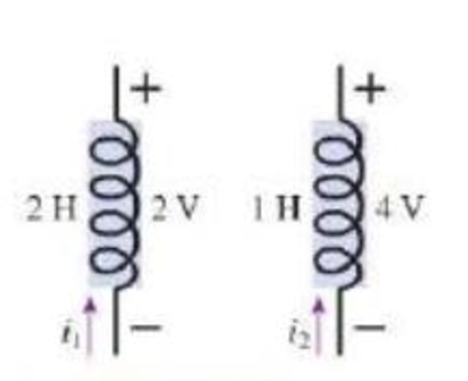
Figure Q26.17 shows two inductors and the potential difference across them at time t = 0 s.
a. Can you tell which of these inductors has the larger current flowing through it at t = 0 s? If so, which one? If not, why not?
b. Can you tell through which inductor the current is changing more rapidly at t = 0 s? If so, which one? If not, why not?
FIGURE Q26.17
Expert Solution & Answer
Want to see the full answer?
Check out a sample textbook solution
Students have asked these similar questions
A resistor of resistance R = 10 Ω is connected in series with an inductor of L = 15 mH. The RL combination is connected to a variable voltage power supply (V = 4.5 V) by a switch as shown.
a. What is the time constant (τ) of the combination in seconds?
b. The power supply is set to maintain a constant voltage of V = 4.5 V and the switch is closed. Calculate the current, in amperes, through the circuit at t = 0.29 ms after the switch is closed.
c. Calculate the current through the circuit, in amperes, after the switch has been closed for a long time.
W
R₂
a
a. What is the potential drop on the inductor?
R₁
m
Two resistors, R₁ = 125 § and R2 = 325 92, an inductor L = 3.7 mH, a 16 V battery, and a switch are connected as shown above. The switch has been in position a for a long time.
What is the current through resistor R₁?
What is the current through resistor R₂?
Submit Answer Tries 0/10
L
b. At time t = 0s the switch is moved to position b. What is the time constant of the RL circuit obtained?
Submit Answer Tries 0/10
c. Find the current in this RL circuit when the time t is three-quarters of the time constant from part b.
Submit Answer Tries 0/10
d. At what time has the current decayed to 0.75% of its initial value?
Submit Answer Tries 0/10
Impedance plethysmography is a technique that can be used to detect thrombosis—the presence of clots in a blood vessel—by measuring the electrical resistance of a limb, such as the calf of the leg. In a typical clinical setting, a current of 200 mA is passed through the leg from the upper thigh to the foot. The voltage is measured at two points along the calf separated by 13 cm.a. If the voltage measured is 17 mV, what is the resistance of the calf between the electrodes?b. If the average calf diameter between the electrodes is 12 cm, what is the average resistivity of this part of the leg?
Chapter 26 Solutions
College Physics: A Strategic Approach (4th Edition)
Ch. 26 - Identical resistors are connected to separate 12 V...Ch. 26 - Prob. 2CQCh. 26 - Most battery-powered devices wont work if you put...Ch. 26 - Prob. 4CQCh. 26 - A soldering gun contains a transformer that lowers...Ch. 26 - A 12 V DC power supply is connected to the primary...Ch. 26 - Figure Q26.7 shows three wires wrapped around an...Ch. 26 - Women usually have higher resistance of their arms...Ch. 26 - If you work out enough to visibly increase the...Ch. 26 - Prob. 10CQ
Ch. 26 - Prob. 11CQCh. 26 - Prob. 12CQCh. 26 - The peak current through a capacitor is 2.0 A....Ch. 26 - Prob. 14CQCh. 26 - Prob. 16CQCh. 26 - Figure Q26.17 shows two inductors and the...Ch. 26 - The peak current passing through an inductor is...Ch. 26 - Consider the four circuits in Figure Q26.19. Rank...Ch. 26 - Prob. 20CQCh. 26 - The resonance frequency of a driven RLC circuit is...Ch. 26 - Consider the four circuits in Figure Q26.22. They...Ch. 26 - Prob. 23MCQCh. 26 - An inductor is connected to an AC generator. As...Ch. 26 - A capacitor is connected to an AC generator. As...Ch. 26 - An AC source is connected to a series combination...Ch. 26 - An AC source is connected to a series combination...Ch. 26 - The circuit shown in Figure Q26.28 has a resonance...Ch. 26 - At resonance, a driven RLC circuit has VC = 5.0 V,...Ch. 26 - A driven RLC circuit has VC = 5.0V, VR = 7.0 V,...Ch. 26 - A 200 resistor is connected to an AC source with...Ch. 26 - Figure P26.2 shows voltage and current graphs for...Ch. 26 - A resistor dissipates 2.00 W when the rms voltage...Ch. 26 - The heating element of a hair dryer dissipates...Ch. 26 - A toaster oven is rated at 1600 W for operation at...Ch. 26 - Prob. 6PCh. 26 - A generator produces 40 MW of power and sends it...Ch. 26 - Soles of hoots that are designed to protect...Ch. 26 - The primary coil of a transformer is connected to...Ch. 26 - Prob. 10PCh. 26 - A power pack charging a cell phone battery has an...Ch. 26 - A neon sign transformer has a 450 W AC output with...Ch. 26 - Prob. 13PCh. 26 - Prob. 14PCh. 26 - A generator produces 250 kW of electric power at...Ch. 26 - In an old house, the wires leading lo a 120 V...Ch. 26 - A typical American family uses 1000 kWh of...Ch. 26 - Prob. 18PCh. 26 - The following appliances are connected to a single...Ch. 26 - Prob. 20PCh. 26 - A 60 W (120 V) night light is turned on for an...Ch. 26 - Prob. 22PCh. 26 - The manufacturer of an electric table saw claims...Ch. 26 - John is changing a lightbulb in a lamp, Its a warm...Ch. 26 - In some countries AC outlets near bathtubs are...Ch. 26 - If you touch the terminal of a battery, the small...Ch. 26 - A person standing barefoot on the ground 20 m from...Ch. 26 - A fisherman has netted a torpedo ray. As he picks...Ch. 26 - Problems 30 and 31 concern a high-voltage...Ch. 26 - Problems 30 and 31 concern a high-voltage...Ch. 26 - A 0.30 F capacitor is connected across an AC...Ch. 26 - A 20 F capacitor is connected across an AC...Ch. 26 - The peak current through a capacitor is 10.0 mA....Ch. 26 - Prob. 35PCh. 26 - Prob. 36PCh. 26 - The peak current through a capacitor is 8.0 mA...Ch. 26 - Prob. 38PCh. 26 - A 20 mH inductor is connected across an AC...Ch. 26 - Prob. 40PCh. 26 - A 500 H inductor is connected across an AC...Ch. 26 - An inductor is connected to a 15 kHz oscillator...Ch. 26 - The peak current through an inductor is 12.5 mA...Ch. 26 - A 2.0 mH inductor is connected in parallel with a...Ch. 26 - An FM radio station broadcasts at a frequency of...Ch. 26 - The inductor in the RLC tuning circuit of an AM...Ch. 26 - At what frequency f do a 1.0 F capacitor and a 1.0...Ch. 26 - What capacitor in series with a 100 resistor and...Ch. 26 - What inductor in series with a 100 resistor and a...Ch. 26 - A series RLC circuit has a 200 kHz resonance...Ch. 26 - An RLC circuit with a 10 F capacitor is connected...Ch. 26 - Prob. 52PCh. 26 - A series KLC circuit consists of a 280 resistor,...Ch. 26 - Prob. 54PCh. 26 - Electric outlets in England are 230 V. Alice...Ch. 26 - Prob. 56GPCh. 26 - Prob. 57GPCh. 26 - The voltage across a 60 F capacitor is described...Ch. 26 - Prob. 59GPCh. 26 - An electronics hobbyist is building a radio set to...Ch. 26 - Prob. 61GPCh. 26 - Prob. 62GPCh. 26 - An RLC circuit consists of a 48 resistor, a 200 F...Ch. 26 - Cell Membrane Resistance The capacitance of...Ch. 26 - Cell Membrane Resistance The capacitance of...Ch. 26 - Cell Membrane Resistance The capacitance of...Ch. 26 - Cell Membrane Resistance The capacitance of...Ch. 26 - Halogen Bulbs Halogen bulbs have some differences...Ch. 26 - Halogen Bulbs Halogen bulbs have some differences...Ch. 26 - Halogen Bulbs Halogen bulbs have some differences...Ch. 26 - Halogen Bulbs Halogen bulbs have some differences...
Additional Science Textbook Solutions
Find more solutions based on key concepts
Using Figure 3.14 as a guide, do you agree with the friend who reasons that a boxer should be able to deliver m...
Conceptual Integrated Science
Two identical satellites are going in opposite directions in the same circular orbit when they collide head-on....
Essential University Physics (3rd Edition)
During which season (summer or winter) is the Sun highest in the sky at noon? Hint: Consider the drawing showin...
Lecture- Tutorials for Introductory Astronomy
The Scope and Scale of Physics Some have described physics as a “search for simplicity.” Explain why this might...
University Physics Volume 1
Why should there be a force between two dipoles, which each have zero net charge?
Essential University Physics: Volume 2 (3rd Edition)
The Rankine temperature scale (abbreviatedR) uses the same size degrees as Fahrenheit, but measured up from abs...
An Introduction to Thermal Physics
Knowledge Booster


Learn more about
Need a deep-dive on the concept behind this application? Look no further. Learn more about this topic, physics and related others by exploring similar questions and additional content below.Similar questions
- Each of the three situations in Figure P32.68 shows a resistor in a circuit in which currents are induced. Using Lenzs law, determine whether the current in each situation is from a to b or from b to a. a. If the current I in the wire in Figure P32.68A is increased from zero to I, what is the direction of the current induced across the resistor R? b. The switch in Figure P32.68B is initially closed and is thrown open at t = 0. What is the direction of the current induced across the resistor R immediately afterward? c. A bar magnet is brought close to the circuit shown in Figure P32.68C. What is the direction of the current induced across the resistor R?arrow_forwardIn the circuit of Figure P27.25, the switch S has been open for a long time. It is then suddenly closed. Determine the time constant (a) before the switch is closed and (b) after the switch is closed. (c) Let the switch be closed at t = 0. Determine the current in the switch as a function of time. Figure P27.25 Problems 25 and 26.arrow_forwardFigure P29.84 shows a circuit that consists of two identical emf devices. If R1 = R2 = R and the switch is closed, find an expression (in terms of R and ) for the current I that is in the branch from point a to b.arrow_forward
- The peak current passing through an inductor is 2.0 A. What is the peak current ifa. The peak emf ε0 is doubled?b. The inductance L is doubled?c. The frequency f is doubled?arrow_forwardPlease asaparrow_forwardFor the given circuit switch is opened at t=0 after being closed for a long time. R=40 Ohm, C=25mF, L=10H is (1 5 V 1) If i,(t) = 10 u(t)A a. iz(0") =? b. i(t) =? 2) If i,(t) = e-3t u(t)A a. i,(0) =? b. i(t) =?arrow_forward
- An RLC circuit consists of a 69.3 2 resistor, a 3.66 µF capacitor, and a 73.5 mH inductor. Initially, the voltage across the capacitor is 1.20 V, and no current is flowing in the circuit. What is the magnitude of the charge on the capacitor after 0.0104 s? It is not acceptable to let w' = w. i nCarrow_forwardYour laptop has wireless communications connectivity, and you might even have a wireless keyboard or mouse. But there’s one wire you haven’t been able to get rid of yet—the power cord.Researchers are working on ways to circumvent the need for a direct electrical connection for power, and they are experiencing some success. Recently, investigators were able to use current flowing through a primary coil to power a 60 W lightbulb connected to a secondary coil 2.0 m away, with approximately 15% efficiency. The coils were large and the efficiency low, but it’s a start. The wireless power transfer system is outlined in Figure VI.2. An AC supply generates a current through the primary coil, creating a varying magnetic field. This field induces a current in the secondary coil, which is connected to a resistance (the lightbulb) and a capacitor that sets the resonance frequency of the secondary circuit to…arrow_forwardR1 S R3. R2 4. Determine in the current in each resistor given that R1 = R2 = R3 = 1N, the capacitance C = 0.5 µF, and potential across the batter of E = 2V when the switch is closed at t = 0. Determine then after some time (t = 0) after the switch is closed the currents in each resistor.arrow_forward
- a. What is the voltage output (in V) of a transformer used for rechargeable flashlight batteries, if its primary has 510 turns, its secondary 8 turns, and the input voltage is 120 V? b. What input current (in mA) is required to produce a 4.00 A output? c.What is the power input (in W)?arrow_forwardThe 4.00 A current through a 1.30 H inductor is dissipated by a 2.00 Ω resistor in a circuit like that in the figure below with the switch in position 2. a. What is the initial energy in the inductor? b. How long will it take the current to decline to 15.00% of its initial value? c. Calculate the average power dissipated in the inductor. d. What is the ratio of the initial power dissipated by the resistor to the average power dissipated by the inductor?arrow_forwardIn Figure P20.14, what is the direction ofthe current induced in the resistor at theinstant the switch is closed?arrow_forward
arrow_back_ios
SEE MORE QUESTIONS
arrow_forward_ios
Recommended textbooks for you
 Physics for Scientists and Engineers: Foundations...PhysicsISBN:9781133939146Author:Katz, Debora M.Publisher:Cengage Learning
 Physics for Scientists and Engineers with Modern ...PhysicsISBN:9781337553292Author:Raymond A. Serway, John W. JewettPublisher:Cengage Learning
 Physics for Scientists and EngineersPhysicsISBN:9781337553278Author:Raymond A. Serway, John W. JewettPublisher:Cengage Learning
 Principles of Physics: A Calculus-Based TextPhysicsISBN:9781133104261Author:Raymond A. Serway, John W. JewettPublisher:Cengage Learning
 Physics for Scientists and Engineers, Technology ...PhysicsISBN:9781305116399Author:Raymond A. Serway, John W. JewettPublisher:Cengage Learning
 College PhysicsPhysicsISBN:9781938168000Author:Paul Peter Urone, Roger HinrichsPublisher:OpenStax College
Physics for Scientists and Engineers: Foundations...
Physics
ISBN:9781133939146
Author:Katz, Debora M.
Publisher:Cengage Learning
Physics for Scientists and Engineers with Modern ...
Physics
ISBN:9781337553292
Author:Raymond A. Serway, John W. Jewett
Publisher:Cengage Learning
Physics for Scientists and Engineers
Physics
ISBN:9781337553278
Author:Raymond A. Serway, John W. Jewett
Publisher:Cengage Learning
Principles of Physics: A Calculus-Based Text
Physics
ISBN:9781133104261
Author:Raymond A. Serway, John W. Jewett
Publisher:Cengage Learning
Physics for Scientists and Engineers, Technology ...
Physics
ISBN:9781305116399
Author:Raymond A. Serway, John W. Jewett
Publisher:Cengage Learning
College Physics
Physics
ISBN:9781938168000
Author:Paul Peter Urone, Roger Hinrichs
Publisher:OpenStax College
What is Electromagnetic Induction? | Faraday's Laws and Lenz Law | iKen | iKen Edu | iKen App; Author: Iken Edu;https://www.youtube.com/watch?v=3HyORmBip-w;License: Standard YouTube License, CC-BY