(a)
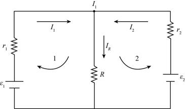
The diagram of the circuit.
(a)
Answer to Problem 83P
The diagram is shown in figure (1).
Explanation of Solution
Calculation:
The diagram of the electric circuit is shown below,

Figure (1)
Conclusion:
Therefore, the diagram is shown in figure (1).
(b)
The current in each branch of the circuit.
(b)
Answer to Problem 83P
The current
Explanation of Solution
Formula used:
The expression for Kirchhoff’s law in first loop is given by,
The expression for Kirchhoff’s law in second loop is given by,
The expression for current in loop 1 is given by,
Calculation:
The expression for Kirchhoff’s law in first loop is calculated as,
The expression for Kirchhoff’s law in second loop is calculated as,
From equation (1) and (2),
Substitute
The
Conclusion:
Therefore, the current
(c)
The power supplied by second battery.
(c)
Answer to Problem 83P
The power supplied by second battery is
Explanation of Solution
Formula used:
The expression for power received by first battery is given by,
The expression for power received by second battery is given by,
The expression for power dissipated in load resistance is given by,
Calculation:
The expression for power received by first battery is calculated as,
The expression for power received by second battery is calculated as,
The power dissipated in load resistance is calculated as,
Conclusion:
Therefore, the power supplied by second battery is
Want to see more full solutions like this?
Chapter 25 Solutions
EBK PHYSICS FOR SCIENTISTS AND ENGINEER
- Consider the circuit shown in the figure below. (Assume L = 5.20 m and R2 = 440 Ω.) (a) When the switch is in position a, for what value of R1 will the circuit have a time constant of 15.4 µs? (b) What is the current in the inductor at the instant the switch is thrown to position b?arrow_forwardCan someone helparrow_forwardCan someone help mearrow_forward
- A particle in a box between x=0 and x=6 has the wavefunction Psi(x)=A sin(2πx). How muchenergy is required for the electron to make a transition to Psi(x)= A’ sin(7π x/3). Draw anapproximate graph for the wavefunction. Find A and A'arrow_forwardA proton is moving with 10^8 m/s speed. Find the De Broglie wavelength associated with theproton and the frequency of that wave.arrow_forwardFind the wavelength of the photon if a (Li--) electron makes a transition from n=4 to n=3. Findthe Bohr radius for each state.arrow_forward
- A photon with wavelength 3000 nm hits a stationary electron. After the collision electron isscattered to 60 degrees. Find the wavelength and frequency of the scattered photon.arrow_forwardA metal has threshold frequency 10^15. Calculate the maximum kinetic energy of the ejectedelectron if a laser beam with wavelength 1.5 10^-7 m is projected on the metal.arrow_forwardDetermine the direction of the vector V, B, or ♬ that is missing from the pair of vectors shown in each scenario. Here, u is the velocity vector of a moving positive charge, B is a constant and uniform magnetic field, and F is the resulting force on the moving charge. 1. 2. 3. B OB F 4. ↑F F 5. 怔 ↑ ↑F Answer Bank 6. ↑ TE Farrow_forward
- Two point charges (+9.80 nC and -9.80 nC) are located 8.00 cm apart. Let U=0 when all of the charges are separated by infinite distances. What is the potential energy if a third point charge q=-4.20 nC is placed at point b? 8.00 cm 8.00 cm 4.00 +4.00 +4.00- cm cm cm HJarrow_forward! Required information Two chloride ions and two sodium ions are in water, the "effective charge" on the chloride ions (CI¯) is −2.00 × 10⁻²¹ C and that of the sodium ions (Na+) is +2.00 x 10⁻²¹ C. (The effective charge is a way to account for the partial shielding due to nearby water molecules.) Assume that all four ions are coplanar. CT Na+ Na+ 30.0° 45.0% с сг L. where a = 0.300 nm, b = 0.710 nm, and c = 0.620 nm. What is the direction of electric force on the chloride ion in the lower right-hand corner in the diagram? Enter the angle in degrees where positive indicates above the negative x-axis and negative indicates below the positive x-axis.arrow_forwardA pendulum has a 0.4-m-long cord and is given a tangential velocity of 0.2 m/s toward the vertical from a position 0 = 0.3 rad. Part A Determine the equation which describes the angular motion. Express your answer in terms of the variable t. Express coefficients in radians to three significant figures. ΜΕ ΑΣΦ vec (t)=0.3 cos (4.95t) + 0.101 sin (4.95t) Submit Previous Answers Request Answer × Incorrect; Try Again; 6 attempts remainingarrow_forward
 Principles of Physics: A Calculus-Based TextPhysicsISBN:9781133104261Author:Raymond A. Serway, John W. JewettPublisher:Cengage Learning
 College PhysicsPhysicsISBN:9781305952300Author:Raymond A. Serway, Chris VuillePublisher:Cengage Learning
 College PhysicsPhysicsISBN:9781285737027Author:Raymond A. Serway, Chris VuillePublisher:Cengage Learning
 College PhysicsPhysicsISBN:9781938168000Author:Paul Peter Urone, Roger HinrichsPublisher:OpenStax College
 Physics for Scientists and Engineers: Foundations...PhysicsISBN:9781133939146Author:Katz, Debora M.Publisher:Cengage Learning


