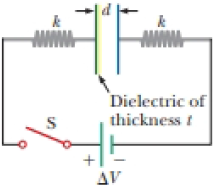
This problem is a continuation of Problem 45. You are part of a team working in a machine parts mechanic’s shop. An important customer has asked your company to provide springs with a very precise force constant k. You devise the electrical circuit shown in Figure P25.45 to measure the spring constant of each of the springs to be provided to the customer.
The circuit consists of two identical, parallel metal plates connected to identical metal springs, a switch, and a battery with emf ΔV. With the switch open, the plates are uncharged, are separated by a distance d, and have a capacitance C.
To provide a comparison value for the spring constant that you found in Problem 45, you slide a slab of material with dielectric constant κ and thickness t between the plates, so that it is in contact with one of the plates as shown in Figure P25.50. When the switch is closed, the plates become charged and attract each other. The distance between the plates changes by a factor f, after which the plates are in equilibrium between the spring forces and the attractive electric force between the plates. To keep the plates from going into oscillations, you hold each plate with insulating gloves as the switch is closed and apply a force on the plates that allows them to move together at a slow constant speed until they are at the equilibrium separation, at which point you can release the plates. Find an expression for the spring constant in terms of C, d, ΔV, k, t, and f.
Figure P25.50
Trending nowThis is a popular solution!
Chapter 25 Solutions
Physics for Scientists and Engineers
- A Pairs of parallel wires or coaxial cables are two conductors separated by an insulator, so they have a capacitance. For a given cable, the capacitance is independent of the length if the cable is very long. A typical circuit model of a cable is shown in Figure P27.87. It is called a lumped-parameter model and represents how a unit length of the cable behaves. Find the equivalent capacitance of a. one unit length (Fig. P27.87A), b. two unit lengths (Fig. P27.87B), and c. an infinite number of unit lengths (Fig. P27.87C). Hint: For the infinite number of units, adding one more unit at the beginning does not change the equivalent capacitance.arrow_forwardThe circuit in Figure P21.59 has been connected for a long time. (a) What is the potential difference across the capacitor? (b) If the battery is disconnected from the circuit, over what time interval does the capacitor discharge to one-tenth its initial voltage?arrow_forwardThe circuit in Figure P27.85 shows four capacitors connected to a battery. The switch S is initially open, and all capacitors have reached their final charge. The capacitances are C1 = 6.00 F, C2 = 12.00 F, C3 = 8.00 F, and C4 = 4.00 F. a. Find the potential difference across each capacitor and the charge stored in each. b. The switch is now closed. What is the new final potential difference across each capacitor and the new charge stored in each? Figure P27.85arrow_forward
- The circuit shown in Figure P28.78 is set up in the laboratory to measure an unknown capacitance C in series with a resistance R = 10.0 M powered by a battery whose emf is 6.19 V. The data given in the table are the measured voltages across the capacitor as a function of lime, where t = 0 represents the instant at which the switch is thrown to position b. (a) Construct a graph of In (/v) versus I and perform a linear least-squares fit to the data, (b) From the slope of your graph, obtain a value for the time constant of the circuit and a value for the capacitance. v(V) t(s) In (/v) 6.19 0 5.56 4.87 4.93 11.1 4.34 19.4 3.72 30.8 3.09 46.6 2.47 67.3 1.83 102.2arrow_forwardFor the four capacitors in the circuit shown in Figure P27.30, CA = 1.00 F, CB = 4.00 F, CC = 2.00 F, and CD = 3.00 F. What is the equivalent capacitance between points a and b? Figure P27.30arrow_forward(a) Determine the equilibrium charge on the capacitor in the circuit of Figure P27.46 as a function of R. (b) Evaluate the charge when R = 10.0 . (c) Can the charge on the capacitor be zero? If so, for what value of R? (d) What is the maximum possible magnitude of the charge on the capacitor? For what value of R is it achieved? (c) Is it experimentally meaningful to take R = ? Explain your answer. If so, what charge magnitude does it imply? Figure P27.46arrow_forward
- The capacitances of three capacitors are in the ratio 1:2:3. Their equivalent capacitance when all three are in parallel is 120.0 pF greater than when all three are in series. Determine the capacitance of each capacitor.arrow_forwardA pair of capacitors with capacitances CA = 3.70 F and CB = 6.40 F are connected in a network. What is the equivalent capacitance of the pair of capacitors if they are connected a. in parallel and b. in series?arrow_forwardSuppose you need to measure the potential difference between the points in Figure P29.4. Assume the voltmeter reading is the potential difference between the two leads: V = Vred Vblack. For each of the following measurements, determine at which point you would connect the red lead and at which point you would connect the black lead: a. Vb Va. b. Vc Vb. c. Vd Vc. d. Va Vd. FIGURE P29.4 Problems 4, 5, and 6.arrow_forward
- A 90.0-V battery is connected to a capacitor with capacitance CA. The capacitor is charged and then disconnected from the battery. Capacitor CA is next connected to a second, uncharged capacitor with capacitance CB = 22.0 F. If the voltage across the capacitors in parallel is measured to be 55.0 V, what is the capacitance CA?arrow_forwardMeasuring Blood Flow. Blood contains positive and negative ions and thus is a conductor. A blood vessel, therefore, can be viewed as an electrical wire. We can even picture the flowing blood as a series of parallel conducting slabs whose thickness is the diameter 5.00 mm of the vessel moving with speed. (See in the following figure.( Figure 1)) Figure X XBX X XX X X X X d 1 of 1 V If you expect that the blood will be flowing at 15.3 cm/s for a vessel 5.00 mm in diameter, what strength of magnetic field will you need to produce a potential difference of 1.00 mV ? Express your answer with the appropriate units. B = Submit Part C 0 R = μA Submit Value X Incorrect; Try Again; 5 attempts remaining T Previous Answers Request Answer = VE ΑΣΦ Determine the volume rate of flow (R). (Note: Although the method developed here is useful in measuring the rate of blood flow in a vessel, it is limited to use in surgery because measurement of the potential & must be made directly across the vessel.)…arrow_forwardA capacitor with a capacitance of 3.5 μF is initially uncharged. It is connected in series with a switch of negligible resistance, a resistor with a resistance of 19 kΩ, and a battery that has a potential difference of 170 V. a. Immediately after the switch is closed, what is the voltage drop VC, in volts, across the capacitor? b. Immediately after the switch is closed, what is the voltage drop VR, in volts, across the resistor? c. Immediately after the switch is closed, what is the current, in amperes, through the resistor? d. Find an expression for the time after the switch is closed when the current in the resistor equals half its maximum value. e. What is the charge Q, in microcoulombs, on the capacitor when the current in the resistor equals one half its maximum value.arrow_forward
- Physics for Scientists and Engineers: Foundations...PhysicsISBN:9781133939146Author:Katz, Debora M.Publisher:Cengage LearningPhysics for Scientists and EngineersPhysicsISBN:9781337553278Author:Raymond A. Serway, John W. JewettPublisher:Cengage LearningPhysics for Scientists and Engineers with Modern ...PhysicsISBN:9781337553292Author:Raymond A. Serway, John W. JewettPublisher:Cengage Learning
- Physics for Scientists and Engineers, Technology ...PhysicsISBN:9781305116399Author:Raymond A. Serway, John W. JewettPublisher:Cengage LearningPrinciples of Physics: A Calculus-Based TextPhysicsISBN:9781133104261Author:Raymond A. Serway, John W. JewettPublisher:Cengage Learning