
EBK VECTOR MECHANICS FOR ENGINEERS: STA
11th Edition
ISBN: 8220102809888
Author: BEER
Publisher: YUZU
expand_more
expand_more
format_list_bulleted
Concept explainers
Videos
Textbook Question
Chapter 2.5, Problem 2.108P
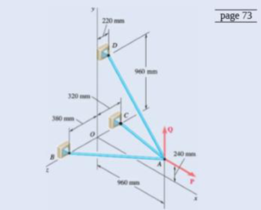
Fig. P2.107 and P2.108
2.108 Three cables are connected at A, where the forces P and Q are applied as shown. Knowing that P = 1200 N, determine the values of Q for which cable AD is taut.
Expert Solution & Answer

Trending nowThis is a popular solution!

Students have asked these similar questions
1 - Clearly identify the system and its mass and energy exchanges between each system and its surroundings by drawing a box to represent the system boundary, and showing the exchanges by input and output arrows. You may want to search and check the systems on the Internet in case you are not familiar with their operations.
A pot with boiling water on a gas stove
A domestic electric water heater
A motor cycle driven on the roadfrom thermodynamics
You just need to draw and put arrows on the first part a b and c
7. A distributed load
w(x) = 4x1/3
acts on the beam AB shown in Figure 7, where x is measured in meters and w is in kN/m. The
length of the beam is L = 4 m. Find the moment of the resultant force about the point B.
w(x) per unit length
L
Figure 7
B
4. The press in Figure 4 is used to crush a small rock at E. The press comprises three links ABC,
CDE and BG, pinned to each other at B and C, and to the ground at D and G. Sketch free-body
diagrams of each component and hence determine the force exerted on the rock when a vertical
force F = 400 N is applied at A.
210
80
80
C
F
200
B
80
E
60%
-O-D
G
All dimensions in mm.
Figure 4
Chapter 2 Solutions
EBK VECTOR MECHANICS FOR ENGINEERS: STA
Ch. 2.1 - Two forces are applied as shown to a hook....Ch. 2.1 - Two forces are applied as shown to a bracket...Ch. 2.1 - Prob. 2.3PCh. 2.1 - Prob. 2.4PCh. 2.1 - A stake is being pulled out of the ground by means...Ch. 2.1 - A telephone cable is clamped at A to the pole AB....Ch. 2.1 - A telephone cable is clamped at A to the pole AB....Ch. 2.1 - A disabled automobile is pulled by means of two...Ch. 2.1 - A disabled automobile is pulled by means of two...Ch. 2.1 - Two forces are applied as shown to a hook support....
Ch. 2.1 - A steel tank is to be positioned in an excavation....Ch. 2.1 - A steel tank is to be positioned in an excavation....Ch. 2.1 - A steel tank is to be positioned in an excavation....Ch. 2.1 - For the hook support of Prob. 2.10, determine by...Ch. 2.1 - Prob. 2.15PCh. 2.1 - Solve Prob. 2.1 by trigonometry.Ch. 2.1 - Solve Prob. 2.4 by trigonometry.Ch. 2.1 - For the stake of Prob. 2.5, knowing that the...Ch. 2.1 - Prob. 2.19PCh. 2.1 - Prob. 2.20PCh. 2.2 - Determine the x and y components of each of the...Ch. 2.2 - Determine the x and y components of each of die...Ch. 2.2 - Prob. 2.23PCh. 2.2 - 2.23 and 2.24 Determine the x and y components of...Ch. 2.2 - Member BC exerts on member AC a force P directed...Ch. 2.2 - Member BD exerts on member ABC a force P directed...Ch. 2.2 - The hydraulic cylinder BC exerts cm member AB a...Ch. 2.2 - Cable AC exerts on beam AD a force P directed...Ch. 2.2 - The hydraulic cylinder BD exerts on member ABC a...Ch. 2.2 - The guy wire BD exerts on the telephone pole AC a...Ch. 2.2 - Determine the resultant of the three forces of...Ch. 2.2 - Determine the resultant of the three forces of...Ch. 2.2 - Determine the resultant of the three forces of...Ch. 2.2 - Determine the resultant of the three forces of...Ch. 2.2 - Knowing that = 35, determine the resultant of the...Ch. 2.2 - Prob. 2.36PCh. 2.2 - Knowing that = 40, determine the resultant of the...Ch. 2.2 - Knowing that = 75, determine the resultant of the...Ch. 2.2 - Prob. 2.39PCh. 2.2 - Prob. 2.40PCh. 2.2 - PROBLEM 2.41 Determine (a) the required tension in...Ch. 2.2 - PROBLEM 2.42 For the block of Problems 2.37 and...Ch. 2.3 - Two cables are tied together at C and loaded as...Ch. 2.3 - Two forces of magnitude TA = 8 kips and TB = 15...Ch. 2.3 - The 60-lb collar A can slide on a frictionless...Ch. 2.3 - A chairlift has been stopped in the position...Ch. 2.3 - Two cables are tied together at C and are loaded...Ch. 2.3 - Two cables are tied together at C and are loaded...Ch. 2.3 - Prob. 2.45PCh. 2.3 - Two cables are tied together at C and are loaded...Ch. 2.3 - 2.47 Two cables are tied together at C and are...Ch. 2.3 - Knowing that = 20, determine the tension (a) in...Ch. 2.3 - Two cables are tied together at C and are loaded...Ch. 2.3 - Two cables are tied together at C and are loaded...Ch. 2.3 - Prob. 2.51PCh. 2.3 - 2.52 Two forces P and Q are applied as shown to an...Ch. 2.3 - A welded connection is in equilibrium under the...Ch. 2.3 - A welded connection is in equilibrium under the...Ch. 2.3 - A sailor is being rescued using a boatswains chair...Ch. 2.3 - A sailor is being rescued using a boatswains chair...Ch. 2.3 - For the cables of Prob. 2.44, find the value of ...Ch. 2.3 - For the cables of Prob. 2.46, it is known that the...Ch. 2.3 - For the situation described in Fig. P2.48,...Ch. 2.3 - 2.60 Two cables tied together at C are loaded as...Ch. 2.3 - A movable bin and its contents have a combined...Ch. 2.3 - Free-Body Diagram...Ch. 2.3 - Collar A is connected as shown to a 50-lb load and...Ch. 2.3 - Collar A is connected as shown to a 50-lb load and...Ch. 2.3 - 2.65 Three forces are applied to a bracket as...Ch. 2.3 - A 200-kg crate is to be supported by the...Ch. 2.3 - A 600-lb crate is supported by several...Ch. 2.3 - Solve parts b and d of Prob. 2.67, assuming that...Ch. 2.3 - A load Q is applied to the pulley C, which can...Ch. 2.3 - An 1800-N load Q is applied to pulley C, which can...Ch. 2.4 - Prob. 2.71PCh. 2.4 - Prob. 2.72PCh. 2.4 - A gun is aimed at a point A located 35 east of...Ch. 2.4 - Solve Prob. 2.73 assuming that point A is located...Ch. 2.4 - Prob. 2.75PCh. 2.4 - Prob. 2.76PCh. 2.4 - Cable AB is 65 ft long, and the tension in that...Ch. 2.4 - PROBLEM 2.78 Cable AC is 70 ft long, and the...Ch. 2.4 - Prob. 2.79PCh. 2.4 - Prob. 2.80PCh. 2.4 - 2.81 A force acts at the origin of a coordinate...Ch. 2.4 - A force acts at the origin of a coordinate system...Ch. 2.4 - A force F of magnitude 210 N acts at the origin of...Ch. 2.4 - Prob. 2.84PCh. 2.4 - 2.85 A frame ABC is supported in part by cable DBE...Ch. 2.4 - Prob. 2.86PCh. 2.4 - In order to move a wrecked truck, two cables are...Ch. 2.4 - In order to move a wrecked truck, two cables are...Ch. 2.4 - A rectangular plate is supported by three cables...Ch. 2.4 - A rectangular plate is supported by three cables...Ch. 2.4 - Find the magnitude and direction of the resultant...Ch. 2.4 - Find the magnitude and direction of the resultant...Ch. 2.4 - Knowing that the tension is 425 lb in cable AB and...Ch. 2.4 - Knowing that the tension is 510 lb in cable AB and...Ch. 2.4 - Prob. 2.95PCh. 2.4 - For the plate of Prob. 2.89; determine the...Ch. 2.4 - The boom OA carries a load P and is supported by...Ch. 2.4 - Prob. 2.98PCh. 2.5 - Three cables are used to tether a balloon as...Ch. 2.5 - A container of mass m = 120 kg is supported by...Ch. 2.5 - A 150-lb cylinder is supported by two cables AC...Ch. 2.5 - A transmission tower is held by three guy wires...Ch. 2.5 - A container is supported by three cables that are...Ch. 2.5 - A container is supported by three cables that are...Ch. 2.5 - Three cables are used to tether a balloon as...Ch. 2.5 - Three cables are used to tether a balloon as...Ch. 2.5 - Prob. 2.103PCh. 2.5 - Prob. 2.104PCh. 2.5 - Prob. 2.105PCh. 2.5 - Prob. 2.106PCh. 2.5 - Three cables are connected at A, where the forces...Ch. 2.5 - Fig. P2.107 and P2.108 2.108 Three cables are...Ch. 2.5 - A rectangular plate is supported by three cables...Ch. 2.5 - A rectangular plate is supported by three cables...Ch. 2.5 - A transmission tower is held by three guy wires...Ch. 2.5 - A transmission tower is held by three guy wires...Ch. 2.5 - In trying to move across a slippery icy surface, a...Ch. 2.5 - Fig. P2.113 2.114 Solve Prob. 2.113 assuming that...Ch. 2.5 - For the rectangular plate of Probs. 2.109 and...Ch. 2.5 - PROBLEM 2.116 For the cable system of Problems...Ch. 2.5 - PROBLEM 2.117 For the cable system of Problems...Ch. 2.5 - Prob. 2.118PCh. 2.5 - Prob. 2.119PCh. 2.5 - Three wires are connected at point D, which is...Ch. 2.5 - A container of weight W is suspended from ring A,...Ch. 2.5 - Knowing that the tension in cable AC of the system...Ch. 2.5 - Prob. 2.123PCh. 2.5 - Prob. 2.124PCh. 2.5 - Fig. P2.113 2.114 Solve Prob. 2.113 assuming that...Ch. 2.5 - Prob. 2.126PCh. 2 - Prob. 2.127RPCh. 2 - Prob. 2.128RPCh. 2 - A hoist trolley is subjected to the three forces...Ch. 2 - Knowing that = 55 and that boom AC exerts on pin...Ch. 2 - Two cables are tied together at C and loaded as...Ch. 2 - Two cables tied together at C are loaded as shown....Ch. 2 - The end of the coaxial cable AE is attached to the...Ch. 2 - Knowing that the tension in cable AC is 2130 N,...Ch. 2 - Find the magnitude and direction of the resultant...Ch. 2 - Prob. 2.136RPCh. 2 - Collars A and B are connected by a 25-in.-lang...Ch. 2 - Fig. P2.137 and P2.138 2.138 Collars A and B are...
Knowledge Booster


Learn more about
Need a deep-dive on the concept behind this application? Look no further. Learn more about this topic, mechanical-engineering and related others by exploring similar questions and additional content below.Similar questions
- 2. Figure 2 shows a device for lifting bricks and concrete blocks. It comprises two compo- nents ABC and BD, with a frictionless pin at B. Determine the minimum coefficient of friction required at A and D if the device is to work satisfactorily. W all dimensions in inches Figure 2 Darrow_forward1. The shaft AD in Figure 1 supports two pulleys at B and C of radius 200 mm and 250 mm respectively. The shaft is supported in frictionless bearings at A and D and is rotating clockwise (when viewed from the right) at a constant speed of 300 rpm. Only bearing A can support thrust. The tensions T₁ = 200 N, T₂ = 400 N, and T3 = 300 N. The distances AB = 120 mm, BC = 150 mm, and CD120 mm. Find the tension 74 and the reaction forces at the bearings. A T fo Figure 1arrow_forward5. Figure 5 shows a two-dimensional idealization of the front suspension system for a car. During cornering, the road exerts a vertical force of 5 kN and a leftward horizontal force of 1.2 kN on the tire, which is of 510 mm diameter. Draw free-body diagrams of each component and determine the forces transmitted between them. 250 A -320 B 170 D 170 -220-220- all dimensions in mm. Figure 5arrow_forward
- 8. The force F in Figure 8 is 120 lb and the angle 0 = 25°. Find the axial force N, the shear force V and the bending moment M at the point K which is midway between B and C and illustrate their directions on a sketch of the segment KCD. E -0 B K అ D H 7 A- all dimensions in inches Figure 8 Ꮎ G Farrow_forward6. Determine the coordinates x, y of the centroid of the area shaded in Figure 6. y y=x³ Figure 6 3arrow_forward3. Use the method of sections to determine the forces in the members BD, CD, CE in the struc- ture of Figure 3. A B D 4 kN 6 kN all dimensions in meters. Figure 3arrow_forward
- A pipeline engineer is considering alternative natural gas pipeline routings. The first route is mostly over land and the second is primarily undersea. Both pipelines will need some valve and fitting replacements in year 25. Cost data for each route is shown in Table P2.21. Notice that the undersea route has a higher initial cost due to higher installation costs and extra corrosion protection for the pipeline. However, the undersea route has cheaper security and maintenance costs which substantially reduces annual costs. The MARR for the project is 15%. Determine which route should be pursued based on a present worth analysis.arrow_forwardThe state of stress at a point is σ = -4.00 kpsi, σy Tyz = 8.000 kpsi, and T₂ = -14.00 kpsi. What is the maximum shear stress for this case? The maximum shear stress is kpsi. = 16.00 kpsi, σ = -14.00 kpsi, Try = 11.00 kpsi,arrow_forwardThe initial cost of a proposed heat recovery system is $375,000. The annual operation andmaintenance costs are projected to be $12,000. The salvage value of the system at the end of itsuseful life (projected to be 30 years) is $60,000. The annual savings in fuel costs resulting fromthis system are estimated to be $55,000 per year.a. Assuming annual compounding, determine the rate of return for this heat recovery system.b. If management has set the MARR to be 15% for a heat recovery system like this, what is themaximum initial cost that can be spent on the system (assuming that all other costs and incomesare the same)?arrow_forward
- The initial cost of a machine for a production facility is $225,000. The machine is expected tolast for 10 years with no salvage value. The company’s tax rate is 49% and SLD is used todepreciate the machine. For this type of depreciation, the tax life of the machine is considered 8years and its salvage value is $5,000. The after-tax rate of return is 14.3%. Determine the uniformannual before-tax cash flow.arrow_forwardThree alternatives are being considered for an air cleaning system. All three systems have a lifeof 10 years with no salvage value. System A has an initial cost of $29,000. During the first fiveyears of operation, the annual costs to operate system A are $5,000. During the second five years,the annual cost of system A increases to $16,000. System B has an initial cost of $43,000. Theannual cost to operate system B is $4,000, however, after the first year, this cost increases by$1,600 per year. System C has an initial cost of $58,000 with an annual cost of $2,400. System Crequires two upgrades: one during year 4 which costs $6,000, and the other during year 8 whichcosts $3,000. The MARR for this project is 17%. Determine which air cleaning system should beinstalled based on an economic analysis.arrow_forwardShow all work as much as you can and box out answersarrow_forward
arrow_back_ios
SEE MORE QUESTIONS
arrow_forward_ios
Recommended textbooks for you
 Elements Of ElectromagneticsMechanical EngineeringISBN:9780190698614Author:Sadiku, Matthew N. O.Publisher:Oxford University Press
 Mechanics of Materials (10th Edition)Mechanical EngineeringISBN:9780134319650Author:Russell C. HibbelerPublisher:PEARSON
 Thermodynamics: An Engineering ApproachMechanical EngineeringISBN:9781259822674Author:Yunus A. Cengel Dr., Michael A. BolesPublisher:McGraw-Hill Education
 Control Systems EngineeringMechanical EngineeringISBN:9781118170519Author:Norman S. NisePublisher:WILEY
 Mechanics of Materials (MindTap Course List)Mechanical EngineeringISBN:9781337093347Author:Barry J. Goodno, James M. GerePublisher:Cengage Learning
 Engineering Mechanics: StaticsMechanical EngineeringISBN:9781118807330Author:James L. Meriam, L. G. Kraige, J. N. BoltonPublisher:WILEY
Elements Of Electromagnetics
Mechanical Engineering
ISBN:9780190698614
Author:Sadiku, Matthew N. O.
Publisher:Oxford University Press
Mechanics of Materials (10th Edition)
Mechanical Engineering
ISBN:9780134319650
Author:Russell C. Hibbeler
Publisher:PEARSON
Thermodynamics: An Engineering Approach
Mechanical Engineering
ISBN:9781259822674
Author:Yunus A. Cengel Dr., Michael A. Boles
Publisher:McGraw-Hill Education
Control Systems Engineering
Mechanical Engineering
ISBN:9781118170519
Author:Norman S. Nise
Publisher:WILEY
Mechanics of Materials (MindTap Course List)
Mechanical Engineering
ISBN:9781337093347
Author:Barry J. Goodno, James M. Gere
Publisher:Cengage Learning
Engineering Mechanics: Statics
Mechanical Engineering
ISBN:9781118807330
Author:James L. Meriam, L. G. Kraige, J. N. Bolton
Publisher:WILEY
Everything About COMBINED LOADING in 10 Minutes! Mechanics of Materials; Author: Less Boring Lectures;https://www.youtube.com/watch?v=N-PlI900hSg;License: Standard youtube license