EBK VECTOR MECHANICS FOR ENGINEERS: STA
12th Edition
ISBN: 8220106797044
Author: BEER
Publisher: YUZU
expand_more
expand_more
format_list_bulleted
Concept explainers
Videos
Textbook Question
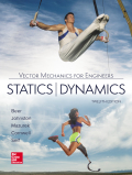
Chapter 2.5, Problem 2.105P
A 12-lb circular plate of 7-in. radius is supported as shown by three wires, each of 25-in. length. Determine the tension in each wire, knowing that α = 30°.
Expert Solution & Answer
Want to see the full answer?
Check out a sample textbook solution
Students have asked these similar questions
A piston-cylinder device initially contains 0.08 m^3 of nitrogen gas at 130
kPa and 170°C. The nitrogen is expanded to a pressure of 80 kPa via
isentropic expansion. Determine the final temperature and the boundary
work done by the system during this process.
A Carnot (ideal) heat pump is to be used to heat a house and maintain it at 22°C
in winter. On a day when the average outdoor temperature remains at about 0°C,
the house is estimated to lose heat at a rate of 65,000 kJ/h. If the heat pump
consumes 6 kW of power while operating, determine:
(a) how long the heat pump ran on that day
(b) the total heating costs, assuming an average price of 11¢/kWh for electricity
(c) the heating cost for the same day if an 85% efficient electric furnace is used
instead of a heat pump.
From the information in the image, I needed to find the orientation of U relative to Q in vector basis q_hat. I transformed the euler angle/axis representation to euler parameters. Then I got its conjugate in order to get the euler parameter in N frame relative to Q. The problem gave the euler angle/axis representation in Q frame relative to N, so I needed to find the conjugate. Then I used the euler parameter rule of successive rotation to find the final euler parameters that describe the orientation of U relative to Q. However that orientation is in n_hat which is the intermediate frame. How do I get the final result in q_hat?
Chapter 2 Solutions
EBK VECTOR MECHANICS FOR ENGINEERS: STA
Ch. 2.1 - Two forces are applied as shown to a hook....Ch. 2.1 - Two forces are applied as shown to a bracket...Ch. 2.1 - Two forces P and Q are applied as shown at point A...Ch. 2.1 - Two forces P and Q are applied as shown at point A...Ch. 2.1 - A stake is being pulled out of the ground by means...Ch. 2.1 - A telephone cable is clamped at A to the pole AB....Ch. 2.1 - A telephone cable is clamped at A to the pole AB....Ch. 2.1 - A disabled automobile is pulled by means of two...Ch. 2.1 - A disabled automobile is pulled by means of two...Ch. 2.1 - Two forces are applied as shown to a hook support....
Ch. 2.1 - A steel tank is to be positioned in an excavation....Ch. 2.1 - A steel tank is to be positioned in an excavation....Ch. 2.1 - A steel tank is to be positioned in an excavation....Ch. 2.1 - For the hook support of Prob. 2.10, determine by...Ch. 2.1 - The barge B is pulled by two tugboats A and C. At...Ch. 2.1 - Solve Prob. 2.1 by trigonometry.Ch. 2.1 - Solve Prob. 2.4 by trigonometry.Ch. 2.1 - For the stake of Prob. 2.5, knowing that the...Ch. 2.1 - Two structural members A and B are bolted to a...Ch. 2.1 - Two structural members A and B are bolted to a...Ch. 2.2 - Determine the x and y components of each of the...Ch. 2.2 - Determine the x and y components of each of die...Ch. 2.2 - Determine the x and y components of each of the...Ch. 2.2 - Determine the x and y components of each of the...Ch. 2.2 - Member BC exerts on member AC a force P directed...Ch. 2.2 - Member BD exerts on member ABC a force P directed...Ch. 2.2 - The hydraulic cylinder BC exerts cm member AB a...Ch. 2.2 - Cable AC exerts on beam AD a force P directed...Ch. 2.2 - The hydraulic cylinder BD exerts on member ABC a...Ch. 2.2 - The guy wire BD exerts on the telephone pole AC a...Ch. 2.2 - Determine the resultant of the three forces of...Ch. 2.2 - Determine the resultant of the three forces of...Ch. 2.2 - Determine the resultant of the three forces of...Ch. 2.2 - Determine the resultant of the three forces of...Ch. 2.2 - Knowing that = 35, determine the resultant of the...Ch. 2.2 - Knowing that the tension in cable BC is 725 N,...Ch. 2.2 - Knowing that = 40, determine the resultant of the...Ch. 2.2 - Knowing that = 75, determine the resultant of the...Ch. 2.2 - PROBLEM 2.39 A collar that can slide on a vertical...Ch. 2.2 - Prob. 2.40PCh. 2.2 - PROBLEM 2.41 Determine (a) the required tension in...Ch. 2.2 - PROBLEM 2.42 For the block of Problems 2.37 and...Ch. 2.3 - Two cables are tied together at C and loaded as...Ch. 2.3 - Two forces of magnitude TA = 8 kips and TB = 15...Ch. 2.3 - The 60-lb collar A can slide on a frictionless...Ch. 2.3 - A chairlift has been stopped in the position...Ch. 2.3 - Two cables are tied together at C and are loaded...Ch. 2.3 - Two cables are tied together at C and are loaded...Ch. 2.3 - Two cables are tied together at C and loaded as...Ch. 2.3 - Two cables are tied together at C and are loaded...Ch. 2.3 - Two cables are tied together at C and are loaded...Ch. 2.3 - Knowing that = 20, determine the tension (a) in...Ch. 2.3 - Two cables are tied together at C and are loaded...Ch. 2.3 - Two cables are tied together at C and are loaded...Ch. 2.3 - Two forces P and Q are applied as shown to an...Ch. 2.3 - Prob. 2.52PCh. 2.3 - A welded connection is in equilibrium under the...Ch. 2.3 - A welded connection is in equilibrium under the...Ch. 2.3 - A sailor is being rescued using a boatswains chair...Ch. 2.3 - A sailor is being rescued using a boatswains chair...Ch. 2.3 - For the cables of Prob. 2.44, find the value of ...Ch. 2.3 - For the cables of Prob. 2.46, it is known that the...Ch. 2.3 - For the situation described in Fig. P2.48,...Ch. 2.3 - Two cables tied together at C are loaded as shown....Ch. 2.3 - A movable bin and its contents have a combined...Ch. 2.3 - Free-Body Diagram...Ch. 2.3 - Collar A is connected as shown to a 50-lb load and...Ch. 2.3 - Collar A is connected as shown to a 50-lb load and...Ch. 2.3 - A cable loop of length 1.5 m is placed around a...Ch. 2.3 - A 200-kg crate is to be supported by the...Ch. 2.3 - A 600-lb crate is supported by several...Ch. 2.3 - Solve parts b and d of Prob. 2.67, assuming that...Ch. 2.3 - A load Q is applied to the pulley C, which can...Ch. 2.3 - An 1800-N load Q is applied to pulley C, which can...Ch. 2.4 - Determine (a) the x, y, and z components of the...Ch. 2.4 - Determine (a) the x, y, and z components of the...Ch. 2.4 - A gun is aimed at a point A located 35 east of...Ch. 2.4 - Solve Prob. 2.73 assuming that point A is located...Ch. 2.4 - Prob. 2.75PCh. 2.4 - Prob. 2.76PCh. 2.4 - Cable AB is 65 ft long, and the tension in that...Ch. 2.4 - PROBLEM 2.78 Cable AC is 70 ft long, and the...Ch. 2.4 - Prob. 2.79PCh. 2.4 - Determine the magnitude and direction of the force...Ch. 2.4 - Prob. 2.81PCh. 2.4 - A force acts at the origin of a coordinate system...Ch. 2.4 - A force F of magnitude 210 N acts at the origin of...Ch. 2.4 - Prob. 2.84PCh. 2.4 - Two cables BG and BH are attached to frame ACD as...Ch. 2.4 - Two cables BG and BH are attached to frame ACD as...Ch. 2.4 - In order to move a wrecked truck, two cables are...Ch. 2.4 - In order to move a wrecked truck, two cables are...Ch. 2.4 - A rectangular plate is supported by three cables...Ch. 2.4 - A rectangular plate is supported by three cables...Ch. 2.4 - Find the magnitude and direction of the resultant...Ch. 2.4 - Find the magnitude and direction of the resultant...Ch. 2.4 - Knowing that the tension is 425 lb in cable AB and...Ch. 2.4 - Knowing that the tension is 510 lb in cable AB and...Ch. 2.4 - For the frame of Prob. 2.85, determine the...Ch. 2.4 - For the plate of Prob. 2.89; determine the...Ch. 2.4 - The boom OA carries a load P and is supported by...Ch. 2.4 - Prob. 2.98PCh. 2.5 - Three cables are used to tether a balloon as...Ch. 2.5 - A container of mass m = 120 kg is supported by...Ch. 2.5 - A 150-lb cylinder is supported by two cables AC...Ch. 2.5 - A transmission tower is held by three guy wires...Ch. 2.5 - A container is supported by three cables that are...Ch. 2.5 - A container is supported by three cables that are...Ch. 2.5 - Three cables are used to tether a balloon as...Ch. 2.5 - Three cables are used to tether a balloon as...Ch. 2.5 - A crate is supported by three cables as shown....Ch. 2.5 - A crate is supported by three cables as shown....Ch. 2.5 - A 12-lb circular plate of 7-in. radius is...Ch. 2.5 - Prob. 2.106PCh. 2.5 - Three cables are connected at A, where the forces...Ch. 2.5 - Fig. P2.107 and P2.108 2.108 Three cables are...Ch. 2.5 - A rectangular plate is supported by three cables...Ch. 2.5 - A rectangular plate is supported by three cables...Ch. 2.5 - A transmission tower is held by three guy wires...Ch. 2.5 - A transmission tower is held by three guy wires...Ch. 2.5 - In trying to move across a slippery icy surface, a...Ch. 2.5 - Fig. P2.113 2.114 Solve Prob. 2.113 assuming that...Ch. 2.5 - For the rectangular plate of Probs. 2.109 and...Ch. 2.5 - PROBLEM 2.116 For the cable system of Problems...Ch. 2.5 - PROBLEM 2.117 For the cable system of Problems...Ch. 2.5 - Three cables are connected at D, where an upward...Ch. 2.5 - Prob. 2.119PCh. 2.5 - Three wires are connected at point D, which is...Ch. 2.5 - A container of weight W is suspended from ring A,...Ch. 2.5 - Knowing that the tension in cable AC of the system...Ch. 2.5 - A container of weight W is suspended from ring A....Ch. 2.5 - For the system of Prob. 2.123, determine W and P...Ch. 2.5 - Fig. P2.113 2.114 Solve Prob. 2.113 assuming that...Ch. 2.5 - Prob. 2.126PCh. 2 - Two forces P and Q are applied to the lid of a...Ch. 2 - Determine the x and y components of each of the...Ch. 2 - A hoist trolley is subjected to the three forces...Ch. 2 - Knowing that = 55 and that boom AC exerts on pin...Ch. 2 - Two cables are tied together at C and loaded as...Ch. 2 - Two cables tied together at C are loaded as shown....Ch. 2 - The end of the coaxial cable AE is attached to the...Ch. 2 - Knowing that the tension in cable AC is 2130 N,...Ch. 2 - Find the magnitude and direction of the resultant...Ch. 2 - Cable BAC passes through a frictionless ring A and...Ch. 2 - Collars A and B are connected by a 25-in.-lang...Ch. 2 - Fig. P2.137 and P2.138 2.138 Collars A and B are...
Knowledge Booster


Learn more about
Need a deep-dive on the concept behind this application? Look no further. Learn more about this topic, mechanical-engineering and related others by exploring similar questions and additional content below.Similar questions
- A proposed method of power generation involves collecting and storing solar energy in large artificial lakes a few meters deep, called solar ponds. Solar energy is absorbed by all parts of the pond, and the water temperature rises everywhere. The top part of the pond, however, loses much of the heat it absorbs to the atmosphere, and as a result, the cool surface water serves as insulation for the bottom part of the pond and helps trap the energy there. Usually, salt is planted at the bottom of the pond to prevent the rise of this hot water to the top. A heat engine that uses an organic fluid, such as alcohol, as the working fluid can be operated between the top and the bottom portions of the pond. If the water temperature is 27°C near the surface and 72°C near the bottom of the pond, determine the maximum thermal efficiency that this power plant can have. Treat the cycle as an ideal heat engine. Would a heat engine operating under these temperature conditions (27°C and 72°C) be…arrow_forwardA standard Carnot heat engine cycle is executed in a closed system between the temperature limits of 320 and 1350 K, with air as the working fluid. The pressures before and after the isothermal compression are 150 and 300 kPa, respectively. Sketch the TS diagram for this cycle. If the net work output per cycle is 0.75 kJ, determine the efficiency of the cycle and the heat transfer to the air (working fluid) per cycle.arrow_forwardPROBLEM 10: A sleeve in the form of a circular tube of length L is Nut placed around a bolt and fitted between washers at each end. The nut is then turned until it is just snug. Use material properties as follows: For the sleeve, as = 21 x 106/°C and Es = 100 GPa Washer Bolt ·L· Sleeve Bolt head For the bolt, αB = 10 × 10-6/°C and EB = 200 GPa. 1. Calculate the temperature rise that is required to produce a compressive stress of 25 MPa in the sleeve.arrow_forward
- This problem illustrates that the factor of safety for a machine element depends on the particular point selected for analysis. Here you are to compute factors of safety, based upon the distortion-energy theory, for stress elements at A and B of the member shown in the figure. This bar is made of AISI 1006 cold-drawn steel and is loaded by the forces F = 1.100 kN, P = 8.00 kN, and T = 50.00 N·m. Given: Sy = 280 MPa. B -100 mm- 15-mm D. a) What is the value of the axial stress at point A? b)What is the value of the shear stress at point A? c)Determine the value of the Von Mises stress at point A. P Farrow_forwardThe three steel wires, each of cross-sectional area 0.05 in2, support the weight W. Theirunstressed lengths are 74.98 ft, 74.99 ft, and 75.00 ft. Use E = 29 x 106 psi.1. Find the stress (psi) in the longest wire if W = 1500 lb.2. Determine the stress in the shortest wire if W = 500 lb ANSWERS: 6130 psi; 6930 psiarrow_forward1: The concrete column is reinforced using four steel reinforcing rods, each having a diameter of 18 mm. Determine the stress in the concrete and the steel if the column is subjected to an axial load of 800 kN. Est = 200 GPa, Ec = 25 GPa. Complete fbd.arrow_forward
- 5: As shown, two aluminum rods AB and BC, hinged to rigid supports, arepinned together at B to carry a vertical load P = 6000 lb. If each rod has a crosssectional area of 0.60 in2 and E = 10 x 106 psi. Use α = θ = 30⁰. Calculate the change in length (in) of rod AB and indicate if it elongates orshortens. Calculate the vertical displacement of B (in) and horizontal displacement of B (in). Complete fbd.arrow_forward2: The rigid bar supports the uniform distributedload of 6 kip/ft. Determine the force in each cable if each cable has a cross-sectional area of 0.05 in^2 , and E = 31(10)^3 ksi.arrow_forwardIn (Figure 1), take m₁ = 4 kg and mB = 4.6 kg. Determine the z component of the angular momentum Ho of particle A about point O. Determine the z component of the angular momentum Ho of particle B about point O. Suppose that 5 m 8 m/s 4 m 1.5 m 4 m B MB 1 m 2 m 5 30° 6 m/s MAarrow_forward
- The two disks A and B have a mass of 4 kg and 6 kg, respectively. They collide with the initial velocities shown. The coefficient of restitution is e = 0.75. Suppose that (VA)1 = 6 m/s, (VB)₁ = 7 m/s. (Figure 1) Determine the magnitude of the velocity of A just after impact. Determine the angle between the x axis and the velocity of A just after impact, measured clockwise from the negative x axis. Determine the magnitude of the velocity of B just after impact. Determine the angle between the x axis and the velocity of B just after impact, measured clockwise from the positive x axis. (VB)1 B (VA)1 60° Line of impactarrow_forwardA hot plane surface is maintained at 100°C, and it is exposed to air at 25°C.The combined heat transfer coefficient between the surface and the air is 25W/m²·K. (same as above). In this task, you are asked to design fins to cool asurface by attaching 3 cm-long, 0.25 cm-diameter aluminum pin fins (thermalconductivity, k = 237 W/m·K) with a center-to-center distance of 0.6 cm. (Tip:do not correct the length). Determine the rate of heat transfer from thefinned structure to the air for a 1 m x 1 m section of the plate.arrow_forwardHeat is generated uniformly in a 4 cm-diameter, 16-cm long solid bar (k=2.4 W/m-K). The temperaturesat the center and at the surface of the bar are measured to be 210 oC and 45 oC, respectively. Calculatethe rate of heat generation within the bar. Solve the relevant energy balance equation and the boundaryconditions to calculate the rate of heat generation within the bar. (6 pts)arrow_forward
arrow_back_ios
SEE MORE QUESTIONS
arrow_forward_ios
Recommended textbooks for you
 Elements Of ElectromagneticsMechanical EngineeringISBN:9780190698614Author:Sadiku, Matthew N. O.Publisher:Oxford University Press
 Mechanics of Materials (10th Edition)Mechanical EngineeringISBN:9780134319650Author:Russell C. HibbelerPublisher:PEARSON
 Thermodynamics: An Engineering ApproachMechanical EngineeringISBN:9781259822674Author:Yunus A. Cengel Dr., Michael A. BolesPublisher:McGraw-Hill Education
 Control Systems EngineeringMechanical EngineeringISBN:9781118170519Author:Norman S. NisePublisher:WILEY
 Mechanics of Materials (MindTap Course List)Mechanical EngineeringISBN:9781337093347Author:Barry J. Goodno, James M. GerePublisher:Cengage Learning
 Engineering Mechanics: StaticsMechanical EngineeringISBN:9781118807330Author:James L. Meriam, L. G. Kraige, J. N. BoltonPublisher:WILEY
Elements Of Electromagnetics
Mechanical Engineering
ISBN:9780190698614
Author:Sadiku, Matthew N. O.
Publisher:Oxford University Press
Mechanics of Materials (10th Edition)
Mechanical Engineering
ISBN:9780134319650
Author:Russell C. Hibbeler
Publisher:PEARSON
Thermodynamics: An Engineering Approach
Mechanical Engineering
ISBN:9781259822674
Author:Yunus A. Cengel Dr., Michael A. Boles
Publisher:McGraw-Hill Education
Control Systems Engineering
Mechanical Engineering
ISBN:9781118170519
Author:Norman S. Nise
Publisher:WILEY
Mechanics of Materials (MindTap Course List)
Mechanical Engineering
ISBN:9781337093347
Author:Barry J. Goodno, James M. Gere
Publisher:Cengage Learning
Engineering Mechanics: Statics
Mechanical Engineering
ISBN:9781118807330
Author:James L. Meriam, L. G. Kraige, J. N. Bolton
Publisher:WILEY
Everything About COMBINED LOADING in 10 Minutes! Mechanics of Materials; Author: Less Boring Lectures;https://www.youtube.com/watch?v=N-PlI900hSg;License: Standard youtube license