Concept explainers
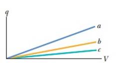
Figure 25-18 shows plots of charge versus potential difference for three parallel-plate capacitors that have the plate areas and separations given in the table. Which plot goes with which capacitor?

Figure 25-18 Question 1.
| Capacitor | Area | Separation |
| 1 | A | d |
| 2 | 2A | d |
| 3 | A | 2d |
To find:
Which plot goes with which capacitor.
Answer to Problem 1Q
Solution:
Plot a goes with the capacitor 2. The plot b goes with capacitor 1 and plot c goes with capacitor 3.
Explanation of Solution
1) Concept:
Using Eq.25-9, we can find capacitance of each capacitor from the given values of area and plate separation. Then using Eq.25-1, we can compare the capacitance from the slopes of the plots. Then, comparing the predictions about the capacitance yielded from both the equations, we can find out which plot goes with which capacitor.
2) Formulae:
i) From Eq.25-1, the charge
ii) From Eq.25-9, the capacitance is
3) Given:
i) For capacitor 1, area is
ii) For capacitor 2, area is
iii) For capacitor 3, area is
iv) For capacitor 1, separation is
v) For capacitor 2, separation is
vi) For capacitor 3, separation is
4) Calculations:
From Eq.25-1, the charge
where
Therefore, the capacitance is given by
From Eq.25-9, the capacitance is
where
Let,
Capacitor 1 has capacitance,
Similarly, Capacitor 2 has capacitance,
And Capacitor 3 has capacitance,
From this, we can interpret that capacitance of capacitor 2 has the greatest value and capacitor 1 has the greater capacitance than that of capacitor 3.
From the graph, we can infer that the plot a has the greatest slope. Hence, the capacitance and the slope of plot b is greater than that of plot c. Hence, corresponding capacitance.
Therefore, we can conclude that, Plot a goes with capacitor 2, plot b goes with capacitor 1 and plot c goes with capacitor 3.
Conclusion:
We can predict about the plots between the charge and the voltage corresponding to capacitors having some area and separation between the plates of capacitor from the slope of the graph and the formula for capacitance.
Want to see more full solutions like this?
Chapter 25 Solutions
Fundamentals of Physics Extended 10e Binder Ready Version + WileyPLUS Registration Card
Additional Science Textbook Solutions
Chemistry
Human Anatomy & Physiology (2nd Edition)
Introductory Chemistry (6th Edition)
Chemistry: Structure and Properties (2nd Edition)
Microbiology: Principles and Explorations
The Cosmic Perspective (8th Edition)
- Find the total capacitance in micro farads of the combination of capacitors shown in the figure below. HF 5.0 µF 3.5 µF №8.0 μLE 1.5 µF Ι 0.75 μF 15 μFarrow_forwardthe answer is not 0.39 or 0.386arrow_forwardFind the total capacitance in micro farads of the combination of capacitors shown in the figure below. 2.01 0.30 µF 2.5 µF 10 μF × HFarrow_forward
- I do not understand the process to answer the second part of question b. Please help me understand how to get there!arrow_forwardRank the six combinations of electric charges on the basis of the electric force acting on 91. Define forces pointing to the right as positive and forces pointing to the left as negative. Rank in increasing order by placing the most negative on the left and the most positive on the right. To rank items as equivalent, overlap them. ▸ View Available Hint(s) [most negative 91 = +1nC 92 = +1nC 91 = -1nC 93 = +1nC 92- +1nC 93 = +1nC -1nC 92- -1nC 93- -1nC 91= +1nC 92 = +1nC 93=-1nC 91 +1nC 92=-1nC 93=-1nC 91 = +1nC 2 = −1nC 93 = +1nC The correct ranking cannot be determined. Reset Help most positivearrow_forwardPart A Find the x-component of the electric field at the origin, point O. Express your answer in newtons per coulomb to three significant figures, keeping in mind that an x component that points to the right is positive. ▸ View Available Hint(s) Eoz = Η ΑΣΦ ? N/C Submit Part B Now, assume that charge q2 is negative; q2 = -6 nC, as shown in (Figure 2). What is the x-component of the net electric field at the origin, point O? Express your answer in newtons per coulomb to three significant figures, keeping in mind that an x component that points to the right is positive. ▸ View Available Hint(s) Eoz= Η ΑΣΦ ? N/Carrow_forward
- 1. A charge of -25 μC is distributed uniformly throughout a spherical volume of radius 11.5 cm. Determine the electric field due to this charge at a distance of (a) 2 cm, (b) 4.6 cm, and (c) 25 cm from the center of the sphere. (a) = = (b) E = (c)Ẻ = = NC NC NCarrow_forward1. A long silver rod of radius 3.5 cm has a charge of -3.9 ис on its surface. Here ŕ is a unit vector ст directed perpendicularly away from the axis of the rod as shown in the figure. (a) Find the electric field at a point 5 cm from the center of the rod (an outside point). E = N C (b) Find the electric field at a point 1.8 cm from the center of the rod (an inside point) E=0 Think & Prepare N C 1. Is there a symmetry in the charge distribution? What kind of symmetry? 2. The problem gives the charge per unit length 1. How do you figure out the surface charge density σ from a?arrow_forward1. Determine the electric flux through each surface whose cross-section is shown below. 55 S₂ -29 S5 SA S3 + 9 Enter your answer in terms of q and ε Φ (a) s₁ (b) s₂ = -29 (C) Φ զ Ερ (d) SA = (e) $5 (f) Sa $6 = II ✓ -29 S6 +39arrow_forward
- No chatgpt pls will upvotearrow_forwardthe cable may break and cause severe injury. cable is more likely to break as compared to the [1] ds, inclined at angles of 30° and 50° to the vertical rings by way of a scaled diagram. [4] I 30° T₁ 3cm 3.8T2 cm 200 N 50° at it is headed due North and its airspeed indicat 240 km/h. If there is a wind of 100 km/h from We e relative to the Earth? [3]arrow_forwardCan you explain this using nodal analysis With the nodes I have present And then show me how many KCL equations I need to write, I’m thinking 2 since we have 2 dependent sourcesarrow_forward
 Principles of Physics: A Calculus-Based TextPhysicsISBN:9781133104261Author:Raymond A. Serway, John W. JewettPublisher:Cengage Learning
 Physics for Scientists and Engineers: Foundations...PhysicsISBN:9781133939146Author:Katz, Debora M.Publisher:Cengage Learning
 Physics for Scientists and EngineersPhysicsISBN:9781337553278Author:Raymond A. Serway, John W. JewettPublisher:Cengage Learning
 Physics for Scientists and Engineers with Modern ...PhysicsISBN:9781337553292Author:Raymond A. Serway, John W. JewettPublisher:Cengage Learning
 Physics for Scientists and Engineers, Technology ...PhysicsISBN:9781305116399Author:Raymond A. Serway, John W. JewettPublisher:Cengage Learning
 College PhysicsPhysicsISBN:9781285737027Author:Raymond A. Serway, Chris VuillePublisher:Cengage Learning


