Particle 1 (with a charge of +5.0 µ C) and particle 2 (with a charge of +3.0 µC ) are fixed in place with separation d = 4.0 cm on the x axis shown in Fig. 24-58 a . Particle 3 can be moved along the x axis to the right of particle 2. Figure 24-58 b gives the electric potential energy U of the three-particle system as a function of the x coordinate of particle 3. The scale of the vertical axis is set by U s = 5.0 J. What is the charge of particle 3? Figure 24-58 Problem 56.
Particle 1 (with a charge of +5.0 µ C) and particle 2 (with a charge of +3.0 µC ) are fixed in place with separation d = 4.0 cm on the x axis shown in Fig. 24-58 a . Particle 3 can be moved along the x axis to the right of particle 2. Figure 24-58 b gives the electric potential energy U of the three-particle system as a function of the x coordinate of particle 3. The scale of the vertical axis is set by U s = 5.0 J. What is the charge of particle 3? Figure 24-58 Problem 56.
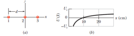
Particle 1 (with a charge of +5.0 µC) and particle 2 (with a charge of +3.0 µC) are fixed in place with separation d = 4.0 cm on the x axis shown in Fig. 24-58a. Particle 3 can be moved along the x axis to the right of particle 2. Figure 24-58b gives the electric potential energy U of the three-particle system as a function of the x coordinate of particle 3. The scale of the vertical axis is set by Us = 5.0 J. What is the charge of particle 3?
For each of the actions depicted below, a magnet and/or metal loop moves with velocity v→ (v→ is constant and has the same magnitude in all parts). Determine whether a current is induced in the metal loop. If so, indicate the direction of the current in the loop, either clockwise or counterclockwise when seen from the right of the loop. The axis of the magnet is lined up with the center of the loop. For the action depicted in (Figure 5), indicate the direction of the induced current in the loop (clockwise, counterclockwise or zero, when seen from the right of the loop). I know that the current is clockwise, I just dont understand why. Please fully explain why it's clockwise, Thank you
A planar double pendulum consists of two point masses \[m_1 = 1.00~\mathrm{kg}, \qquad m_2 = 1.00~\mathrm{kg}\]connected by massless, rigid rods of lengths \[L_1 = 1.00~\mathrm{m}, \qquad L_2 = 1.20~\mathrm{m}.\]The upper rod is hinged to a fixed pivot; gravity acts vertically downward with\[g = 9.81~\mathrm{m\,s^{-2}}.\]Define the generalized coordinates \(\theta_1,\theta_2\) as the angles each rod makes with thedownward vertical (positive anticlockwise, measured in radians unless stated otherwise).At \(t=0\) the system is released from rest with \[\theta_1(0)=120^{\circ}, \qquad\theta_2(0)=-10^{\circ}, \qquad\dot{\theta}_1(0)=\dot{\theta}_2(0)=0 .\]Using the exact nonlinear equations of motion (no small-angle or planar-pendulumapproximations) and assuming the rods never stretch or slip, determine the angle\(\theta_2\) at the instant\[t = 10.0~\mathrm{s}.\]Give the result in degrees, in the interval \((-180^{\circ},180^{\circ}]\).
What are the expected readings of the ammeter and voltmeter for the circuit in the figure below? (R = 5.60 Ω, ΔV = 6.30 V)
ammeter
I =
Chapter 24 Solutions
Fundamentals of Physics Extended 10E WileyPlus 5 Student Package
Need a deep-dive on the concept behind this application? Look no further. Learn more about this topic, physics and related others by exploring similar questions and additional content below.


 Physics for Scientists and Engineers: Foundations...PhysicsISBN:9781133939146Author:Katz, Debora M.Publisher:Cengage Learning
 Principles of Physics: A Calculus-Based TextPhysicsISBN:9781133104261Author:Raymond A. Serway, John W. JewettPublisher:Cengage Learning
 Physics for Scientists and Engineers with Modern ...PhysicsISBN:9781337553292Author:Raymond A. Serway, John W. JewettPublisher:Cengage Learning
 Physics for Scientists and EngineersPhysicsISBN:9781337553278Author:Raymond A. Serway, John W. JewettPublisher:Cengage Learning
 College PhysicsPhysicsISBN:9781305952300Author:Raymond A. Serway, Chris VuillePublisher:Cengage Learning