
Laboratory Manual for Introductory Circuit Analysis
13th Edition
ISBN: 9780133923780
Author: Robert L. Boylestad, Gabriel Kousourou
Publisher: PEARSON
expand_more
expand_more
format_list_bulleted
Concept explainers
Videos
Textbook Question
Chapter 24, Problem 52P
For the three-phase, three-wire system in Fig. 24.58, find the magnitude of the current through each phase of the load, and find the total watts, volt-amperes reactive, volt-amperes, and Fp of the load.
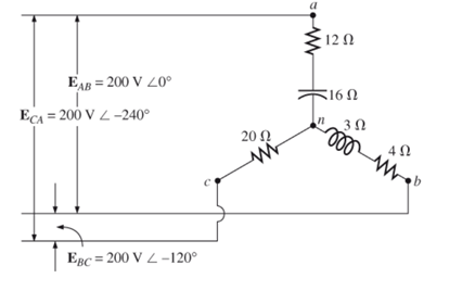
Fig. 24.58
Expert Solution & Answer
Want to see the full answer?
Check out a sample textbook solution
Students have asked these similar questions
not use ai please
Find the equivalent resistance Rab for each of the following. Step by Step
Correct answer given but show full work to get answer no use of AI only handwritten answer
Chapter 24 Solutions
Laboratory Manual for Introductory Circuit Analysis
Ch. 24 - A balanced V load having a 10 resistance in each...Ch. 24 - Repeat Problem 1 if each phase impedance is...Ch. 24 - Repeat Problem 1 if each phase impedance is...Ch. 24 - The phase sequence for the Y-Y system in Fig....Ch. 24 - Repeat Problem 4 if each phase impedance are...Ch. 24 - Repeat Problem 4 if each phase impedance is...Ch. 24 - For the system in Fig. 24.43, find the magnitude...Ch. 24 - Computer the magnitude of the voltage EAB for the...Ch. 24 - For the Y-Y system in Fig. 24.45: a. Find the...Ch. 24 - For the Y-Y system of Fig. 24.46 the impedance of...
Ch. 24 - A balanced load having a 20 resistance in each...Ch. 24 - Repeat Problem 11 if each phase impedance is...Ch. 24 - Repeat Problem 11 if each phase impedance is...Ch. 24 - The phase sequence for the Y- system in Fig....Ch. 24 - Repeat Problem 14 if each phase impedance is...Ch. 24 - Repeat Problem 14 if each phase impedance are...Ch. 24 - Prob. 17PCh. 24 - For the connected load in Fig. 24.49: a. Find the...Ch. 24 - A balanced V load having a 30 resistance in each...Ch. 24 - Repeat Problem 19 if each phase impedance is...Ch. 24 - Prob. 21PCh. 24 - Prob. 22PCh. 24 - Prob. 23PCh. 24 - Repeat Problem 22 if each phase impedance is...Ch. 24 - Prob. 25PCh. 24 - Prob. 26PCh. 24 - Prob. 27PCh. 24 - The phase sequence for the - system in Fig....Ch. 24 - Repeat Problem 28 if each phase impedance is...Ch. 24 - Repeat Problem 28 if each phase impedance is...Ch. 24 - Prob. 31PCh. 24 - Prob. 32PCh. 24 - Prob. 33PCh. 24 - Find the total watts, volt-amperes reactive,...Ch. 24 - Prob. 35PCh. 24 - Find the total watts, volt-amperes reactive,...Ch. 24 - Find the total watts, volt-amperes reactive,...Ch. 24 - Prob. 38PCh. 24 - Prob. 39PCh. 24 - Find the total watts, volt-amperes reactive,...Ch. 24 - A balanced, three-phase, -connected load has a...Ch. 24 - A balanced, three-phase, Y-connected load has a...Ch. 24 - Find the total watts, volt-amperes reactive,...Ch. 24 - The Y-Y system in Fig. 24.53 has a balanced load...Ch. 24 - Prob. 45PCh. 24 - Prob. 46PCh. 24 - Repeat Problem 46 for the network in Fig. 24.47.Ch. 24 - For the three-wire system in Fig. 24.55, properly...Ch. 24 - Sketch three different ways that two wattmeters...Ch. 24 - For the Y- system in Fig. 24.56: Determine the...Ch. 24 - For the system in Fig. 24.57: Calculate the...Ch. 24 - For the three-phase, three-wire system in Fig....
Knowledge Booster


Learn more about
Need a deep-dive on the concept behind this application? Look no further. Learn more about this topic, electrical-engineering and related others by exploring similar questions and additional content below.Similar questions
- Draw the fabrication layers of a transistor with MS junction (Schottky junction).arrow_forwardQ: Draw the fabrication layers of a transistor with MS junction (Schottky junction).arrow_forward+ C/E, 4 TA b IA + 2V C/E 2 +1 - C + V3 - C/EU - ча - V4 + e + /E3 V2 12V a (a) Find currents L, L2 and is (b) Find Voltages V, V2, V3 and V4 - 2A CIEG For each circuit element and the two sources state whether they are ABSORBING SUPPLYING pores and how much poner 13 absorbed or supplied. +arrow_forward
- Please solve part a, b and c Also, find the impulse response g(t) for the systemarrow_forwardConsider the lateral dynamics of a vectored thrust aircraft as described in Example 3.12. Show that the dynamics can be described using the following block diagram: Ꮎ r ալ -mg Σ J82 ע 1 X ms² + cs Use this block diagram to compute the transfer functions from u₁ to 0 and x and show that they satisfy Нои r Js² - mgr Js²' Hau₁ Js2 (ms2+cs)arrow_forwardConsider the system dx ax+u. dt Compute the exponential response of the system and use this to derive the transfer function from u to x. Show that when s = a, a pole of the transfer function, the response to the exponential input u(t) = est is x(t) = eat x(0) + teat. For solving the system with u = eat eat you can't use the transfer function because the denominator is zero. Try using the convolution integral solution with initial conditions set as x(t) = eat x (0) + fo g(t − T)u(T)dT - g(t) is the impulse response of the system.arrow_forward
- dny dn-1y dn-1u dn-24 +a1 + + Any = bi +b₂- + +bnu. dtn dtn-1 dtn-1 dtn-2 a) Let be a root of the characteristic equation 1 sn+a1sn- + +an = : 0. Show that if u(t) = 0, the differential equation has the solution y(t) = e\t. b) Let к be a zero of the polynomial b(s) = b₁s-1+b2sn−2+ Show that if the input is u(t) equation that is identically zero. = .. +bn. ekt, then there is a solution to the differentialarrow_forwarddny dn-1y dn-1u dn-24 +a1 + + Any = bi +b₂- + +bnu. dtn dtn-1 dtn-1 dtn-2 a) Let be a root of the characteristic equation 1 sn+a1sn- + +an = : 0. Show that if u(t) = 0, the differential equation has the solution y(t) = e\t. b) Let к be a zero of the polynomial b(s) = b₁s-1+b2sn−2+ Show that if the input is u(t) equation that is identically zero. = .. +bn. ekt, then there is a solution to the differentialarrow_forwardFor step a), use equations (2) to find the equation for the input impedance equations (2) are V1 = jwL1I1 + jwMI2 and V2 = jwMI1 + jwL2I2 equation for the input impedance: Z1 = V1/I1 = jwL1 + (wM)2/(jwL2 + ZL)arrow_forward
- L (a) Find currents i, and b₂ 2 2 (b) Find the dependent source voltage given as Find voltages V, and (c) V₂ 5i2 (d) For each circuit element in the circuit and the two Sources, state whether they are ABSORBING OF SUPPYING Power and how much power is absorbed or Supplied. + V - 5A +lov- C/E₂ + C/E4 Vz い 5+2 + 1A C/E 5V + シュ 2A + 10Varrow_forward4) A circuit is given as shown. (a) Find currents i, and i2. (b) Find the dependent source voltage given as 5i2 (c) Find voltages V, and V₂ 2 (d) For each circuit element in the circuit and the two Sources, State whether they are ABSORBING, OF SUPPLYING POWER and how much power is absorbed or supplied. + 10V - + 4 CIES C/E + V L₁ 4 1A Y T5A GE -5V + CIES iz 2A 2 52 2 +arrow_forwardDetermine the eigenvalues and eigenvectors of using A = ( 1 -3 3 3 -5 3 6-64 Gauss eliminationarrow_forward
arrow_back_ios
SEE MORE QUESTIONS
arrow_forward_ios
Recommended textbooks for you
 Power System Analysis and Design (MindTap Course ...Electrical EngineeringISBN:9781305632134Author:J. Duncan Glover, Thomas Overbye, Mulukutla S. SarmaPublisher:Cengage Learning
Power System Analysis and Design (MindTap Course ...
Electrical Engineering
ISBN:9781305632134
Author:J. Duncan Glover, Thomas Overbye, Mulukutla S. Sarma
Publisher:Cengage Learning
Fault Analysis in Power Systems part 1a; Author: GeneralPAC: Power System Tutorials;https://www.youtube.com/watch?v=g8itg4MOjok;License: Standard youtube license