
Engineering Mechanics: Statics Plus Mastering Engineering with Pearson eText -- Access Card Package (14th Edition) (Hibbeler, The Engineering Mechanics: Statics & Dynamics Series, 14th Edition)
14th Edition
ISBN: 9780134160689
Author: Russell C. Hibbeler
Publisher: PEARSON
expand_more
expand_more
format_list_bulleted
Videos
Textbook Question
Chapter 2.4, Problem 52P
Show that the resultant force is zero.
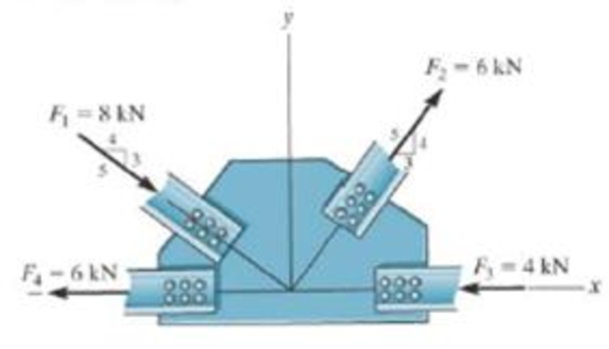
Prob. 2-52
Expert Solution & Answer

Trending nowThis is a popular solution!

Students have asked these similar questions
A 2D incompressible flow has velocitycomponents u= X^2 - 2y^2 and v=aX^b y^c
,where a, b, and c are numbers.
Find the values of a, b, and c
Find the stream function
Please can you assist with the attached question please?
(a) Find a second-order homogeneous linear ODE for which the given functions are
solutions. (b) Show linear independence by the Wronskian. (c) Solve the initial value
problem.
a. cos(5x), sin(5x), y(0) = 3, y'(0) = −5
b. e-2.5x cos(0.3x), e-2.5x sin(0.3x), y(0) = 3, y'(0) = -7.5
Chapter 2 Solutions
Engineering Mechanics: Statics Plus Mastering Engineering with Pearson eText -- Access Card Package (14th Edition) (Hibbeler, The Engineering Mechanics: Statics & Dynamics Series, 14th Edition)
Ch. 2.3 - Then establish the triangle rule, where FR = F1 +...Ch. 2.3 - Then establish the triangle rule to show FR = FU +...Ch. 2.3 - Determine the magnitude of the resultant force...Ch. 2.3 - Determine the magnitude of the resultant force....Ch. 2.3 - Determine the magnitude of the resultant force and...Ch. 2.3 - Resolve the 30-lb force into components along the...Ch. 2.3 - Resolve this force into components acting along...Ch. 2.3 - along the v axis. Prob. F2-6Ch. 2.3 - If = 60 and F = 450 N, determine the magnitude of...Ch. 2.3 - If the magnitude of the resultant force is to be...
Ch. 2.3 - Determine the magnitude of the resultant force FR...Ch. 2.3 - Determine the magnitudes of the two components of...Ch. 2.3 - Solve with F = 350 lb. Prob. 2-4/5Ch. 2.3 - Determine the magnitude of the resultant force FR...Ch. 2.3 - Resolve the force F1 into components acting along...Ch. 2.3 - Resolve the force F2 into components acting along...Ch. 2.3 - If the resultant force acting on the support is to...Ch. 2.3 - Determine the magnitude of the resultant force and...Ch. 2.3 - If = 60, determine the magnitude of the resultant...Ch. 2.3 - Also, what is the magnitude of the resultant...Ch. 2.3 - Resolve this force into two components acting...Ch. 2.3 - Determine the magnitude of F and its component...Ch. 2.3 - Determine the magnitude of F and its direction ....Ch. 2.3 - Determine the required angle (0 45) and the...Ch. 2.3 - Determine the magnitude and direction of the...Ch. 2.3 - Determine the magnitude and direction of the...Ch. 2.3 - What is the component of force acting along member...Ch. 2.3 - Take = 30. Probs. 2-19/20Ch. 2.3 - FR measured counterclockwise from the positive x...Ch. 2.3 - Solve I by first finding the resultant F = F2 + F3...Ch. 2.3 - If F1 = 400 N and F2 = 600 N, determine the angle...Ch. 2.3 - If their lines of action are at an angle apart...Ch. 2.3 - If F1 = 30 lb and F2 = 40 lb, determine the angles...Ch. 2.3 - Determine the magnitude and direction of FA SO...Ch. 2.3 - Determine the magnitude and direction, measured...Ch. 2.3 - What is the minimum magnitude of FR?Ch. 2.3 - directed along the positive x axis, determine the...Ch. 2.3 - If FB = 3 kN and = 45, determine the magnitude of...Ch. 2.3 - If the resultant force of the two tugboats is...Ch. 2.4 - Resolve each force acting on the post into its x...Ch. 2.4 - Determine the magnitude and direction of the...Ch. 2.4 - Determine the magnitude of the resultant force...Ch. 2.4 - determine the magnitude of F and its direction ....Ch. 2.4 - If the magnitude of the resultant force acting on...Ch. 2.4 - Determine the magnitude of the resultant force and...Ch. 2.4 - Determine the magnitude of the resultant force and...Ch. 2.4 - Determine the magnitude of the resultant force and...Ch. 2.4 - Resolve F1 and F2 into their x and y components.Ch. 2.4 - Determine the magnitude of the resultant force and...Ch. 2.4 - Resolve each force acting on the gusset plate into...Ch. 2.4 - Determine the magnitude of the resultant force...Ch. 2.4 - Express each of the three forces acting on the...Ch. 2.4 - Determine the x and y components of F1 and F2....Ch. 2.4 - Determine the magnitude of the resultant force and...Ch. 2.4 - Determine the magnitude of the resultant force and...Ch. 2.4 - Express F1, F2, and F3 as Cartesian vectors.Ch. 2.4 - Determine the magnitude of the resultant force and...Ch. 2.4 - Determine the magnitude of the resultant force and...Ch. 2.4 - Determine the magnitude and direction of the...Ch. 2.4 - Determine the magnitude and orientation of FB so...Ch. 2.4 - measured counterclockwise from the positive y...Ch. 2.4 - Prob. 48PCh. 2.4 - Prob. 49PCh. 2.4 - Express F1, F2, and F3 as Cartesian vectors.Ch. 2.4 - Determine the magnitude of the resultant fore and...Ch. 2.4 - Show that the resultant force is zero. Prob. 2-52Ch. 2.4 - Express F1 and F2 as Cartesian vectors.Ch. 2.4 - Determine the magnitude of the resultant force and...Ch. 2.4 - What is the magnitude of the resultant force?...Ch. 2.4 - If the magnitude of the resultant force acting on...Ch. 2.4 - Set = 30. Probs. 2-56/57Ch. 2.4 - Determine the magnitude and direction of F so...Ch. 2.4 - Prob. 59PCh. 2.6 - Show , , . a) F = {50i + 60j 10k} kN b) F = {40i ...Ch. 2.6 - In each case, establish F as a Cartesian vector,...Ch. 2.6 - Set up the calculation used to find the magnitude...Ch. 2.6 - Determine the coordinate direction angles of the...Ch. 2.6 - Express the force as a Cartesian vector. Prob....Ch. 2.6 - Express the force as a Cartesian vector. Prob....Ch. 2.6 - Express the force as a Cartesian vector. Prob....Ch. 2.6 - Express the force as a Cartesian vector. Prob....Ch. 2.6 - Determine the resultant force acting on the hook....Ch. 2.6 - Determine the magnitudes of the x, y, z components...Ch. 2.6 - If the magnitude of F is 80 N, and = 60 and =...Ch. 2.6 - The component of F in the x-y plane is 7 kN. Prob....Ch. 2.6 - Determine the magnitude and coordinate direction...Ch. 2.6 - Specify the coordinate direction angles of F1 and...Ch. 2.6 - Express each force in Cartesian vector form and...Ch. 2.6 - Determine the coordinate direction angles of F1....Ch. 2.6 - Determine the magnitude and coordinate direction...Ch. 2.6 - Determine the magnitude and coordinate direction...Ch. 2.6 - Determine the magnitude and coordinate direction...Ch. 2.6 - Determine the magnitude and coordinate direction...Ch. 2.6 - Note that F1 lies in the x-y plane.Ch. 2.6 - If the resultant force FR has a magnitude of 150...Ch. 2.6 - Express each force in Cartesian vector form.Ch. 2.6 - Determine the magnitude and coordinate direction...Ch. 2.6 - Express each force as a Cartesian vector.Ch. 2.6 - Determine the resultant of the two forces and...Ch. 2.6 - Determine the magnitude and coordinate direction...Ch. 2.6 - Prob. 78PCh. 2.6 - Determine the coordinate direction angles of the...Ch. 2.6 - Express each force in Cartesian vector form and...Ch. 2.6 - If the coordinate direction angles for F1 are 3 =...Ch. 2.6 - If the coordinate direction angles for F1 are 3 =...Ch. 2.6 - If the direction of the resultant force acting on...Ch. 2.6 - Prob. 84PCh. 2.6 - If = 75, determine the magnitudes of F and Fy....Ch. 2.8 - In each case, establish a position vector from...Ch. 2.8 - In each case, express F as a Cartesian vector....Ch. 2.8 - Express the position vector rAB in Cartesian...Ch. 2.8 - What is the angle ? Prob. F2-20Ch. 2.8 - Prob. 21FPCh. 2.8 - Express the force as a Cartesian vector. Prob....Ch. 2.8 - Determine the magnitude of the resultant force at...Ch. 2.8 - Determine the resultant force at A. Prob. F2-24Ch. 2.8 - Determine the length of the connecting rod AB by...Ch. 2.8 - Express force F as a Cartesian vector; then...Ch. 2.8 - Express each of the forces in Cartesian vector...Ch. 2.8 - If F = {350i 250j 450k} N and cable AB is 9 m...Ch. 2.8 - Prob. 90PCh. 2.8 - If z = 5 m, determine the location +x, +y of point...Ch. 2.8 - Express each of the forces in Cartesian vector...Ch. 2.8 - If FB = 560 N and FC = 700 N, determine the...Ch. 2.8 - If FB = 700 N, and FC = 560 N, determine the...Ch. 2.8 - Express each force as a Cartesian vector. Prob....Ch. 2.8 - Represent each force as a Cartesian vector. Probs....Ch. 2.8 - Determine the magnitude and coordinate direction...Ch. 2.8 - Express the force as a Cartesian vector. Prob....Ch. 2.8 - Express this force as a Cartesian vector acting on...Ch. 2.8 - Determine the magnitude and coordinate direction...Ch. 2.8 - Represent each force as a Cartesian vector and...Ch. 2.8 - The anticipated loading in two of the struts is...Ch. 2.8 - Determine the magnitude and coordinate direction...Ch. 2.8 - If the force in each cable tied to the bin is 70...Ch. 2.8 - Due to symmetry, the tension in the four cables is...Ch. 2.9 - Do not calculate the result. Prob. P2-8Ch. 2.9 - P2.9. In each case, set up the dot product to find...Ch. 2.9 - Determine the angle between the force and the...Ch. 2.9 - Determine the angle between the force and the...Ch. 2.9 - Determine the angle between the force and the...Ch. 2.9 - Determine the projected component of the force...Ch. 2.9 - Find the magnitude of the projected component of...Ch. 2.9 - Determine the components of the force acting...Ch. 2.9 - Determine the magnitudes of the components of the...Ch. 2.9 - Express the force F in Cartesian vector form if it...Ch. 2.9 - Express force F in Cartesian vector form if point...Ch. 2.9 - If the force in each chain has a magnitude of 60...Ch. 2.9 - If the resultant force at O has a magnitude of 130...Ch. 2.9 - Determine the length of the chain, and express the...Ch. 2.9 - Determine the length of the cable and express the...Ch. 2.9 - Prob. 112PCh. 2.9 - Determine the magnitudes of the components of F =...Ch. 2.9 - Determine the angle between the two cables. Prob....Ch. 2.9 - Determine the magnitude of the projection of the...Ch. 2.9 - Determine the angle between the y axis of the...Ch. 2.9 - Determine the magnitudes of the projected...Ch. 2.9 - Determine the angle between cables AB and AC....Ch. 2.9 - Prob. 119PCh. 2.9 - Determine the magnitude of the projected component...Ch. 2.9 - Determine the angle between the two cables...Ch. 2.9 - Determine the angle between the cables AB and AC....Ch. 2.9 - Determine the magnitude of the projected component...Ch. 2.9 - Determine the magnitude of the projected component...Ch. 2.9 - Determine the magnitude of the projection of force...Ch. 2.9 - Determine the magnitude of the projected component...Ch. 2.9 - Determine the angle between pipe segments BA and...Ch. 2.9 - Prob. 128PCh. 2.9 - Determine the magnitude of the projected component...Ch. 2.9 - Determine the angles and made between the axes...Ch. 2.9 - Prob. 131PCh. 2.9 - Express this component as a Cartesian vector....Ch. 2.9 - Prob. 133PCh. 2.9 - Prob. 134PCh. 2.9 - Determine the magnitudes of the components of the...Ch. 2.9 - Determine the magnitudes of the projected...Ch. 2.9 - Prob. 137PCh. 2.9 - Determine the angle between the two cables....Ch. 2.9 - Express the result as a Cartesian vector.Ch. 2.9 - Determine the magnitude of the resultant force FR...Ch. 2.9 - Resolve F into components along the u and v axes...Ch. 2.9 - Determine the magnitude of the resultant force...Ch. 2.9 - Prob. 4RPCh. 2.9 - The cable attach to the tractor at B exerts a...Ch. 2.9 - Prob. 6RPCh. 2.9 - Determine the angle between the edges of the...Ch. 2.9 - Determine the projection of the force F along the...
Additional Engineering Textbook Solutions
Find more solutions based on key concepts
In the following exercises, write a program to carry out the task. The program should use variables for each of...
Introduction To Programming Using Visual Basic (11th Edition)
Milling has two feeds. What are they, and which one is an input parameter to the machine tool?
Degarmo's Materials And Processes In Manufacturing
What is pseudocode?
Starting Out With Visual Basic (8th Edition)
Look at the following function header: der my_function(a, b, c): Now look at the following call to my_function:...
Starting Out with Python (4th Edition)
Porter’s competitive forces model: The model is used to provide a general view about the firms, the competitors...
Management Information Systems: Managing The Digital Firm (16th Edition)
Describe the three types of anomalies that can arise in a table and the negative consequences of each.
Modern Database Management
Knowledge Booster


Learn more about
Need a deep-dive on the concept behind this application? Look no further. Learn more about this topic, mechanical-engineering and related others by exploring similar questions and additional content below.Similar questions
- Solve the IVP. a. y" 16y 17e* ; = y(0) = 6, y'(0) = -2 b. (D² + 41)y = sin(t) + ½ sin(3t) + sin(t) ; y(0) = 0, y'(0) : = 35 31arrow_forwardFind the general solution. a. y' 5y = 3ex - 2x + 1 - b. y" +4y' + 4y = e¯*cos(x) c. (D² + I)y = cos(wt), w² # 1arrow_forwardhandwritten solutions, please!!arrow_forward
- > Homework 4 - Spring 2025.pdf Spring 2025.pdf k 4 - Spring 2025.pdf (447 KB) Due: Thursday, February 27 Page 1 > of 2 ZOOM 1. A simply supported shaft is shown in Figure 1 with wo = 25 N/cm and M = 20 N cm. Use singularity functions to determine the reactions at the supports. Assume EI = 1000 kN cm². M Wo 0 10 20 30 40 50 60 70 80 90 100 110 cm Figure 1 - Problem 1 2. A support hook was formed from a rectangular bar. Find the stresses at the inner and outer surfaces at sections just above and just below O-B. 210 mmarrow_forwardA distillation column with a total condenser and a partial reboiler is separating ethanol andwater at 1.0 atm. Feed is 0.32 mol fraction ethanol and it enters as a saturated liquid at 100mol/s on the optimum plate. The distillate product is a saturated liquid with 80 mol% ethanol.The condenser removes 5615 kW. The bottoms product is 0.05 mol fraction ethanol. AssumeCMO is valid.(a) Find the number of equilibrium stages for this separation. [6 + PR](b) Find how much larger the actual reflux ratio, R, used is than Rmin, i.e. R/Rmin. [3]Note: the heats of vaporization of ethanol and water are λe = 38.58 and λw = 40.645 arrow_forwardWe have a feed that is a binary mixture of methanol and water (60.0 mol% methanol) that issent to a system of two flash drums hooked together. The vapor from the first drum is cooled,which partially condenses the vapor, and then is fed to the second flash drum. Both drumsoperate at 1.0 atm and are adiabatic. The feed to the first drum is 1000 kmol/hr. We desire aliquid product from the first drum that is 35.0 mol% methanol. The second drum operates at afraction vaporized of (V/F)2 = 0.25.(a) Find the liquid flow rate leaving the first flash drum, L1 (kmol/hr). [286 kmol/hr](b) Find the vapor composition leaving the second flash drum, y2. [0.85]arrow_forward
- = The steel curved bar shown has rectangular cross-section with a radial height h = 6 mm and thickness b = 4mm. The radius of the centroidal axis is R = 80 mm. A force P = 10 N is applied as shown. Assume the steel modulus of 207,000 MPa and G = 79.3(103) MPa, repectively. elasticity and shear modulus E = Find the vertical deflection at point B. Use Castigliano's method for a curved flexural member and since R/h > 10, neglect the effect of shear and axial load, thereby assuming that deflection is due to merely the bending moment. Note the inner and outer radii of the curves bar are: r = 80 + ½ (6) = 83 mm, r₁ = 80 − ½ (6) = 77 mm 2 2 Sπ/2 sin² 0 d = √π/² cos² 0 d0 = Π 0 4 大 C R B Parrow_forwardThe steel eyebolt shown in the figure is loaded with a force F = 75 lb. The eyebolt is formed from round wire of diameter d = 0.25 in to a radius R₁ = 0.50 in in the eye and at the shank. Estimate the stresses at the inner and outer surfaces at section A-A. Notice at the section A-A: r₁ = 0.5 in, ro = 0.75 in rc = 0.5 + 0.125 = 0.625 in Ri 200 F FAarrow_forwardI have the fallowing question and solution from a reeds naval arc book. Im just confused as to where this answer came from and the formulas used. Wondering if i could have this answer/ solution broken down and explained in detail. A ship of 7000 tonne displacement has a waterplane areaof 1500 m2. In passing from sea water into river water of1005 kg/m3 there is an increase in draught of 10 cm. Find the Idensity of the sea water. picture of the "answer" is attachedarrow_forward
- Problem A2 long steel tube has a rectangular cross-section with outer dimensions of 20 x 20 mm and a uniform wall thickness of 2. The tube is twisted along its length with torque, T. The tube material is 1045 CD steel with shear yield strength of S,, =315 MPa. Assume shear modulus, G = 79.3GPa. (a) Estimate the maximum torque that can be applied without yielding (b) Estimate the torque required to produce 5 degrees total angle of twist over the length of the tube. (c) What is the maximum torque that can be applied without yielding, if a solid rectangular shaft with dimensions of 20 x 20 is used? You may use the exact solution.arrow_forwardA simply supported beam is loaded as shown. Considering symmetry, the reactions at supports A and B are R₁ = R₂ = wa 2 Using the singularity method, determine the shear force V along the length of the beam as a function of distance x from the support A. A B Ir. 2a За W C R₁₂ x 2. Using the singularity method, determine the bending M along the length of the beam as a function of distance x, from the support A. 3. Using the singularity method, determine the beam slope and deflection along the length of the beam as a function of the distance x, from the support A. Assume the material modulus of elasticity, E and the moment of inertia of the beam cross-section, I are given.arrow_forwardA steel tube, 2 m long, has a rectangular cross-section with outer dimensions of 20 × 30 mm and a uniform wall thickness of 1 mm. The tube is twisted along its length with torque, T. The tube material is 1018 CD steel with shear yield strength of Ssy =185 MPa. Assume shear modulus, G = 79.3GPa. (a) Estimate the maximum torque that can be applied without yielding.- (b) Estimate the torque required to produce 3 degrees total angle of twist over the length of the tube. (c) What is the maximum torque that can be applied without yielding, if a solid rectangular shaft with dimensions of 20 x 30 mm is used? You may use the exact solution:arrow_forward
arrow_back_ios
SEE MORE QUESTIONS
arrow_forward_ios
Recommended textbooks for you
 International Edition---engineering Mechanics: St...Mechanical EngineeringISBN:9781305501607Author:Andrew Pytel And Jaan KiusalaasPublisher:CENGAGE L
International Edition---engineering Mechanics: St...
Mechanical Engineering
ISBN:9781305501607
Author:Andrew Pytel And Jaan Kiusalaas
Publisher:CENGAGE L
How to balance a see saw using moments example problem; Author: Engineer4Free;https://www.youtube.com/watch?v=d7tX37j-iHU;License: Standard Youtube License