
Videos
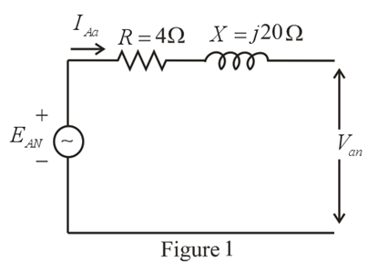
The Y-Y system in Fig. 24.53 has a balanced load and a line impedance
a. The magnitude of each phase voltage of the generator.
b. The magnitude of the line currents.
c. The total power delivered by the source.
d. The power factor angle of the entire load "seen" by the source.
e. The magnitude and angle of the current if
f The magnitude and angle of the phase voltage Van
g. The impedance of the load of each phase in rectangular coordinates.
h. The difference between the power factor of the load and the power factor of the entire system (including Zline.
i. The efficiency of the system.
Want to see the full answer?
Check out a sample textbook solution
Chapter 24 Solutions
Introductory Circuit Analysis (13th Edition)


- Find the Thévenin equivalent circuit for the portions of the networks in Figure external to the elements between points a and b. E = 20 VZ0° + R ww 2 ΚΩ Хо XL 000 6ΚΩ 3 ΚΩ b RLarrow_forwardWhat percentage of the full-load current of a thermally protected continuous-duty motor of more than one Hp can the trip current be, if the full-load current is 15 amperes? Ο 122 Ο 140 156 O 170arrow_forwardQ3arrow_forward
- In thinkercad can you make a parallel series circuit with a resistors and a voltage source explain how the voltage and current moves through the circuit, and explaining all the components, and if you were to break the circuit to find the current how would you do that? Please show visuals if possible.arrow_forwardIn thinkercad can you make a series circuit with a resistors and a voltage source explain how the voltage and current moves through the circuit, and explaining all the components, and if you were to break the circuit to find the current how would you do that? Please show visuals if possible.arrow_forwardIn thinkercad can you make a parallel circuit with a resistors and a voltage source explain how the voltage and current moves through the circuit, and explaining all the components, and if you were to break the circuit to find the current how would you do that? Please show visuals if possiblearrow_forward
- Q1arrow_forward2-2 -Draw V-curves for synchronous motor at no load, half load, and full load? 2-List the advantages of damper bars in synchronous machines? 3-Draw phasor diagram for alternator at unity power factor, and derive EMF equation from it?arrow_forwardconduit bending techniques and the most common anglesarrow_forward
- Question 1 Draw and complex CMOS logic and design the width-to-length ratios (W/L) of the transistors needed to implement the CMOS circuit for the following function (asuume Wp: W₁ = 2:1) n f=AB+CD+E+AD Question 2 Implement the following function using CMOS technology. f = x1(x2x3 + x4) Design the width-to-length ratios (W/L) of the transistors needed to implement the CMOS circuuit for the following function (asuume Wp: W₁ = 2:1) n Question 3 Consider the following three-pole feedback amplifier with a loop gain function: 6000× B T (jf) = 1+j f 2×10³ 1+ j f 3×10⁴ f 1+ j 4×10⁵ If ẞ=38.66×10³ determine the phase margin and the gain margin of this system (if it is stable).arrow_forwardhow to bend conduit in exact angles. and bending angles stepsarrow_forward¡ you need to connect a three phase alternator B (incoming generator) in parallel with alternator A which is connected to an infinite bus bar, what are the necessary conditions to make this connection appen properly? Explain how you can use a three lamps to achieve this connection?arrow_forward
 Power System Analysis and Design (MindTap Course ...Electrical EngineeringISBN:9781305632134Author:J. Duncan Glover, Thomas Overbye, Mulukutla S. SarmaPublisher:Cengage Learning