
Introductory Circuit Analysis (13th Edition)
13th Edition
ISBN: 9780133923605
Author: Robert L. Boylestad
Publisher: PEARSON
expand_more
expand_more
format_list_bulleted
Concept explainers
Videos
Textbook Question
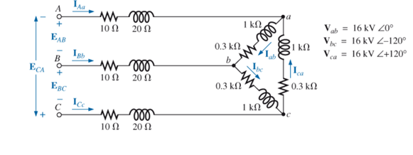
Chapter 24, Problem 18P
For the
a. Find the magnitude and angle of each phase current lab, Ibc, and lca.
b. Calculate the magnitude and angle of each line current lAa, lBb, and lCc.
c. Determine the magnitude and angle of the voltages EAB, EBC, and ECA.
Expert Solution & Answer
Want to see the full answer?
Check out a sample textbook solution
Students have asked these similar questions
+
P = 16 W
w
w
P = 8 W
I
R₁
R2
E
=
RT=322
1- Determine R1, R2, E
ΙΩ
+
30 V
=
-
20 V +
R
2- Use KVL to find the voltage V
- V +
+
8 V
Find the Thévenin equivalent circuit for
the portions of the networks in Figure
external to the elements between points
a and b.
a
R₁
2002
I = 0.1 A 0°
Xc
: 32 Ω
R2
= 6802
20 Ω
фъ
Chapter 24 Solutions
Introductory Circuit Analysis (13th Edition)
Ch. 24 - A balanced V load having a 10 resistance in each...Ch. 24 - Repeat Problem 1 if each phase impedance is...Ch. 24 - Repeat Problem 1 if each phase impedance is...Ch. 24 - The phase sequence for the Y-Y system in Fig....Ch. 24 - Repeat Problem 4 if each phase impedance are...Ch. 24 - Repeat Problem 4 if each phase impedance is...Ch. 24 - For the system in Fig. 24.43, find the magnitude...Ch. 24 - Computer the magnitude of the voltage EAB for the...Ch. 24 - For the Y-Y system in Fig. 24.45: a. Find the...Ch. 24 - For the Y-Y system of Fig. 24.46 the impedance of...
Ch. 24 - A balanced load having a 20 resistance in each...Ch. 24 - Repeat Problem 11 if each phase impedance is...Ch. 24 - Repeat Problem 11 if each phase impedance is...Ch. 24 - The phase sequence for the Y- system in Fig....Ch. 24 - Repeat Problem 14 if each phase impedance is...Ch. 24 - Repeat Problem 14 if each phase impedance are...Ch. 24 - Prob. 17PCh. 24 - For the connected load in Fig. 24.49: a. Find the...Ch. 24 - A balanced V load having a 30 resistance in each...Ch. 24 - Repeat Problem 19 if each phase impedance is...Ch. 24 - Prob. 21PCh. 24 - Prob. 22PCh. 24 - Prob. 23PCh. 24 - Repeat Problem 22 if each phase impedance is...Ch. 24 - Prob. 25PCh. 24 - Prob. 26PCh. 24 - Prob. 27PCh. 24 - The phase sequence for the - system in Fig....Ch. 24 - Repeat Problem 28 if each phase impedance is...Ch. 24 - Repeat Problem 28 if each phase impedance is...Ch. 24 - Prob. 31PCh. 24 - Prob. 32PCh. 24 - Prob. 33PCh. 24 - Find the total watts, volt-amperes reactive,...Ch. 24 - Prob. 35PCh. 24 - Find the total watts, volt-amperes reactive,...Ch. 24 - Find the total watts, volt-amperes reactive,...Ch. 24 - Prob. 38PCh. 24 - Prob. 39PCh. 24 - Find the total watts, volt-amperes reactive,...Ch. 24 - A balanced, three-phase, -connected load has a...Ch. 24 - A balanced, three-phase, Y-connected load has a...Ch. 24 - Find the total watts, volt-amperes reactive,...Ch. 24 - The Y-Y system in Fig. 24.53 has a balanced load...Ch. 24 - Prob. 45PCh. 24 - Prob. 46PCh. 24 - Repeat Problem 46 for the network in Fig. 24.47.Ch. 24 - For the three-wire system in Fig. 24.55, properly...Ch. 24 - Sketch three different ways that two wattmeters...Ch. 24 - For the Y- system in Fig. 24.56: Determine the...Ch. 24 - For the system in Fig. 24.57: Calculate the...Ch. 24 - For the three-phase, three-wire system in Fig....
Knowledge Booster


Learn more about
Need a deep-dive on the concept behind this application? Look no further. Learn more about this topic, electrical-engineering and related others by exploring similar questions and additional content below.Similar questions
- Find the Norton equivalent circuit for the network external to the elements between a and b for the networks in Figure. E1 = 120 V Z 0° R ww 10 Ω Xc XL · 000 802 802 ① I = 0.5 AZ 60° ZL barrow_forwardUsing superposition, determine the current through inductance XL for each network in Figure I = 0.3 A 60° XL 000 802 XC 502 Ω E 10 V0° =arrow_forwardFind the Thévenin equivalent circuit for the portions of the networks in Figure external to the elements between points a and b. E = 20 VZ0° + R ww 2 ΚΩ Хо XL 000 6ΚΩ 3 ΚΩ b RLarrow_forward
- What percentage of the full-load current of a thermally protected continuous-duty motor of more than one Hp can the trip current be, if the full-load current is 15 amperes? Ο 122 Ο 140 156 O 170arrow_forwardQ3arrow_forwardIn thinkercad can you make a parallel series circuit with a resistors and a voltage source explain how the voltage and current moves through the circuit, and explaining all the components, and if you were to break the circuit to find the current how would you do that? Please show visuals if possible.arrow_forward
- In thinkercad can you make a series circuit with a resistors and a voltage source explain how the voltage and current moves through the circuit, and explaining all the components, and if you were to break the circuit to find the current how would you do that? Please show visuals if possible.arrow_forwardIn thinkercad can you make a parallel circuit with a resistors and a voltage source explain how the voltage and current moves through the circuit, and explaining all the components, and if you were to break the circuit to find the current how would you do that? Please show visuals if possiblearrow_forwardQ1arrow_forward
- 2-2 -Draw V-curves for synchronous motor at no load, half load, and full load? 2-List the advantages of damper bars in synchronous machines? 3-Draw phasor diagram for alternator at unity power factor, and derive EMF equation from it?arrow_forwardconduit bending techniques and the most common anglesarrow_forwardQuestion 1 Draw and complex CMOS logic and design the width-to-length ratios (W/L) of the transistors needed to implement the CMOS circuit for the following function (asuume Wp: W₁ = 2:1) n f=AB+CD+E+AD Question 2 Implement the following function using CMOS technology. f = x1(x2x3 + x4) Design the width-to-length ratios (W/L) of the transistors needed to implement the CMOS circuuit for the following function (asuume Wp: W₁ = 2:1) n Question 3 Consider the following three-pole feedback amplifier with a loop gain function: 6000× B T (jf) = 1+j f 2×10³ 1+ j f 3×10⁴ f 1+ j 4×10⁵ If ẞ=38.66×10³ determine the phase margin and the gain margin of this system (if it is stable).arrow_forward
arrow_back_ios
SEE MORE QUESTIONS
arrow_forward_ios
Recommended textbooks for you
 Power System Analysis and Design (MindTap Course ...Electrical EngineeringISBN:9781305632134Author:J. Duncan Glover, Thomas Overbye, Mulukutla S. SarmaPublisher:Cengage Learning
Power System Analysis and Design (MindTap Course ...
Electrical Engineering
ISBN:9781305632134
Author:J. Duncan Glover, Thomas Overbye, Mulukutla S. Sarma
Publisher:Cengage Learning
What is the Difference Between Single Phase and Three Phase???; Author: Electrician U;https://www.youtube.com/watch?v=FEydcr4wJw0;License: Standard Youtube License