
Videos
For the cables of Prob. 2.44, find the value of α for which the tension is as small as possible (a) in cable BC, (b) in both cables simultaneously. In each case, determine the tension in each cable.
(a)
The value of the angle
Answer to Problem 2.57P
The value of the angle
Explanation of Solution
The arrangement of the system is given in Fig. P2.44. The tension in the cable
The free body diagram of the arrangement shown in Fig. P2.44 is given in the Figure
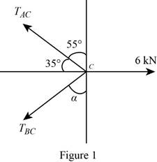
Since the point
The angle between the
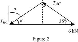
Write the expression for the angle
Apply law of sine to the force triangle in Figure 2.
Conclusion:
From the force triangle the angle
Substitute
Solve equation (I) for
Substitute
Solve equation (I) for
Therefore, the value of the angle
(b)
The value of the angle
Answer to Problem 2.57P
The value of the angle
Explanation of Solution
The free body diagram corresponding to the given arrangement is given in Figure 1
The force triangle become isosceles when the tension in both the cables become the minimum, since the tensions will be equal on both the cables in such situation.
The force triangle corresponding to the minimum tension in both cables
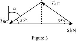
Apply the law of sine to the force triangle given in Figure 3.
Conclusion:
From inspection on the force triangle in Figure 3, the angle
Solve equation (III) for
Solve equation (III) for
Therefore, the value of the angle
Want to see more full solutions like this?
Chapter 2 Solutions
Vector Mechanics for Engineers: Statics


- (read me)arrow_forward(read image)arrow_forwardQu. 13 What are the indices for the Direction 2 indicated by vector in the following sketch? Qu. 14 Determine the indices for the direction A and B shown in the following cubic unit cell. please show all work step by step from material engineeringarrow_forward
- The thin-walled open cross section shown is transmitting torque 7. The angle of twist ₁ per unit length of each leg can be determined separately using the equation 01 = 3Ti GLIC 3 where G is the shear modulus, ₁ is the angle of twist per unit length, T is torque, and L is the length of the median line. In this case, i = 1, 2, 3, and T; represents the torque in leg i. Assuming that the angle of twist per unit length for each leg is the same, show that T= Lic³ and Tmaz = G01 Cmax Consider a steel section with Tallow = 12.40 kpsi. C1 2 mm L1 20 mm C2 3 mm L2 30 mm C3 2 mm L3 25 mm Determine the torque transmitted by each leg and the torque transmitted by the entire section. The torque transmitted by the first leg is | N-m. The torque transmitted by the second leg is N-m. The torque transmitted by the third leg is N-m. The torque transmitted by the entire section is N-m.arrow_forwardPlease help, make sure it's to box out and make it clear what answers go where...arrow_forwardThe cylinder floats in the water and oil to the level shown. Determine the weight of the cylinder. (rho)o=910 kg/m^3arrow_forward
 Elements Of ElectromagneticsMechanical EngineeringISBN:9780190698614Author:Sadiku, Matthew N. O.Publisher:Oxford University Press
 Mechanics of Materials (10th Edition)Mechanical EngineeringISBN:9780134319650Author:Russell C. HibbelerPublisher:PEARSON
 Thermodynamics: An Engineering ApproachMechanical EngineeringISBN:9781259822674Author:Yunus A. Cengel Dr., Michael A. BolesPublisher:McGraw-Hill Education
 Control Systems EngineeringMechanical EngineeringISBN:9781118170519Author:Norman S. NisePublisher:WILEY
 Mechanics of Materials (MindTap Course List)Mechanical EngineeringISBN:9781337093347Author:Barry J. Goodno, James M. GerePublisher:Cengage Learning
 Engineering Mechanics: StaticsMechanical EngineeringISBN:9781118807330Author:James L. Meriam, L. G. Kraige, J. N. BoltonPublisher:WILEY