College Physics: A Strategic Approach (4th Edition)
4th Edition
ISBN: 9780134609034
Author: Randall D. Knight (Professor Emeritus), Brian Jones, Stuart Field
Publisher: PEARSON
expand_more
expand_more
format_list_bulleted
Videos
Textbook Question
Chapter 23, Problem 11CQ
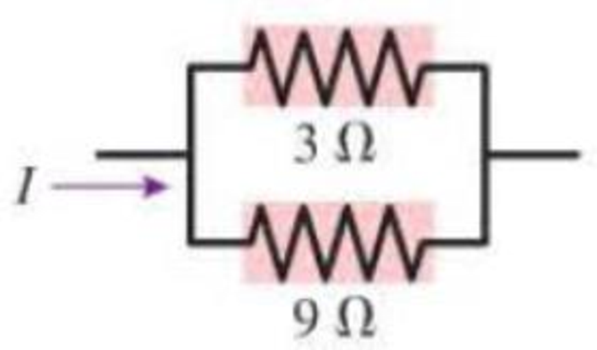
a. In Figure Q23.9, what fraction of current I goes through the 3 Ω resistor?
If the 9 Ω resistor is replaced with a larger resistor, will the fraction of current going through the 3 Ω resistor increase, decrease, or stay the same?
Figure Q23.9
Expert Solution & Answer
Want to see the full answer?
Check out a sample textbook solution
Students have asked these similar questions
a. What is the potential difference across each resistor in Figure P23.6?b. Draw a graph of the potential as a function of the distance traveledthrough the circuit, traveling clockwise from V = 0 V at the lower left corner. See Figure P23.9 for an example of such a graph.
Two batteries supply current to the circuit in the figure. The figure shows the potential difference across two of the resistors and the value of the third resistor. What current is supplied by the batteries?
The current in a circuit with only one battery is 2.0 A. Shown is how the potential changes when going around the circuit in the clockwise direction, starting from the lower left corner. Draw the circuit diagram.
Chapter 23 Solutions
College Physics: A Strategic Approach (4th Edition)
Ch. 23 - Prob. 1CQCh. 23 - Prob. 2CQCh. 23 - Current Iin flows into three resistors connected...Ch. 23 - The circuit in Figure Q23.4 has two resistors,...Ch. 23 - The circuit in Figure Q23.5 has a battery and two...Ch. 23 - Prob. 6CQCh. 23 - Prob. 7CQCh. 23 - In the circuit shown in Figure Q23.6, bulbs A and...Ch. 23 - Figure Q23.7 shows two circuits. The two batteries...Ch. 23 - Figure Q23.8 shows two circuits. The two batteries...
Ch. 23 - a. In Figure Q23.9, what fraction of current I...Ch. 23 - Prob. 12CQCh. 23 - Prob. 13CQCh. 23 - Prob. 14CQCh. 23 - Prob. 15CQCh. 23 - Prob. 16CQCh. 23 - Prob. 17CQCh. 23 - Prob. 18CQCh. 23 - Prob. 19CQCh. 23 - Prob. 20CQCh. 23 - Prob. 21CQCh. 23 - Prob. 22CQCh. 23 - Prob. 23CQCh. 23 - Prob. 24CQCh. 23 - Prob. 25CQCh. 23 - Prob. 26CQCh. 23 - Prob. 27CQCh. 23 - Prob. 28CQCh. 23 - Prob. 29CQCh. 23 - A device to make an electrical measurement of skin...Ch. 23 - Consider the model of nerve conduction in...Ch. 23 - Adding a myelin sheath to an axon results in...Ch. 23 - Prob. 34MCQCh. 23 - Prob. 35MCQCh. 23 - Prob. 36MCQCh. 23 - A metal wire of resistance R is cut into two...Ch. 23 - Prob. 38MCQCh. 23 - Prob. 39MCQCh. 23 - If a cells membrane thickness doubles but the cell...Ch. 23 - If a cells diameter is reduced by 50% without...Ch. 23 - Prob. 42MCQCh. 23 - Draw a circuit diagram tor the circuit of Figure...Ch. 23 - Draw a circuit diagram for the circuit of Figure...Ch. 23 - Draw a circuit diagram for the circuit of Figure...Ch. 23 - In Figure P23.4, what is the current in the wire...Ch. 23 - Prob. 5PCh. 23 - Prob. 6PCh. 23 - a. What are the magnitude and direction of the...Ch. 23 - Prob. 8PCh. 23 - The current in a circuit with only one battery is...Ch. 23 - What is the equivalent resistance of each group of...Ch. 23 - What is the equivalent resistance of each group of...Ch. 23 - Prob. 12PCh. 23 - Prob. 13PCh. 23 - You have a collection of 1.0 k resistors. How can...Ch. 23 - You have a collection of six 1.0 k resistors. What...Ch. 23 - You have six 1.0 k resistors. How can you connect...Ch. 23 - Prob. 17PCh. 23 - Prob. 18PCh. 23 - Prob. 19PCh. 23 - Prob. 20PCh. 23 - Prob. 21PCh. 23 - Prob. 22PCh. 23 - Prob. 23PCh. 23 - Prob. 24PCh. 23 - Prob. 25PCh. 23 - Prob. 26PCh. 23 - Prob. 27PCh. 23 - Prob. 28PCh. 23 - Prob. 29PCh. 23 - Prob. 30PCh. 23 - Prob. 31PCh. 23 - Prob. 32PCh. 23 - Prob. 33PCh. 23 - Prob. 34PCh. 23 - Prob. 35PCh. 23 - A 6.0 F capacitor, a 10 F capacitor, and a 16 F...Ch. 23 - A 6.0 F capacitor, a 10 F capacitor, and a 16 F...Ch. 23 - You need a capacitance of 50 F, but you dont...Ch. 23 - You need a capacitance of 50 F, but you dont...Ch. 23 - Prob. 40PCh. 23 - Prob. 41PCh. 23 - Prob. 42PCh. 23 - Prob. 43PCh. 23 - Prob. 44PCh. 23 - Prob. 45PCh. 23 - Prob. 46PCh. 23 - A 10F capacitor initially charged to 20C is...Ch. 23 - A capacitor charging circuit consists of a...Ch. 23 - Prob. 49PCh. 23 - A 9.0-nm-thick cell membrane undergoes an action...Ch. 23 - A cell membrane has a resistance and a capacitance...Ch. 23 - Changing the thickness of the myelin sheath...Ch. 23 - A particular myelinated axon has nodes spaced 0.80...Ch. 23 - To measure signal propagation in a nerve in the...Ch. 23 - A myelinated axon conducts nerve impulses at a...Ch. 23 - Prob. 56GPCh. 23 - Two 75 W (120 V) lightbulbs are wired in series,...Ch. 23 - Prob. 58GPCh. 23 - A real battery is not just an emf. We can If model...Ch. 23 - Prob. 60GPCh. 23 - Batteries are recharged by connecting them to a...Ch. 23 - Prob. 63GPCh. 23 - Prob. 64GPCh. 23 - Prob. 65GPCh. 23 - Prob. 66GPCh. 23 - What is the ratio P parallel/P series of the total...Ch. 23 - You have a device that needs a voltage reference...Ch. 23 - Prob. 69GPCh. 23 - A circuit youre building needs an ammeter that...Ch. 23 - A circuit youre building needs a voltmeter that...Ch. 23 - For the circuit shown in Figure P23.68, find the...Ch. 23 - You have three 12 F capacitors. Draw diagrams...Ch. 23 - Initially, the switch in Figure P23.70 is in...Ch. 23 - Prob. 75GPCh. 23 - Prob. 76GPCh. 23 - Prob. 77GPCh. 23 - Prob. 78GPCh. 23 - Prob. 79GPCh. 23 - Prob. 80GPCh. 23 - Intermittent windshield wipers use a variable...Ch. 23 - Prob. 82GPCh. 23 - In Example 23.14 we estimated the capacitance of...Ch. 23 - The giant axon of a squid is 0.5 mm in diameter,...Ch. 23 - A cell has a 7.0-nm-thick membrane with a total...Ch. 23 - The Defibrillator A defibrillator is designed to...Ch. 23 - The Defibrillator A defibrillator is designed to...Ch. 23 - The Defibrillator A defibrillator is designed to...Ch. 23 - A defibrillator is designed to pass a large...Ch. 23 - The voltage produced by a single nerve or muscle...Ch. 23 - The voltage produced by a single nerve or muscle...Ch. 23 - The voltage produced by a single nerve or muscle...Ch. 23 - The voltage produced by a single nerve or muscle...
Additional Science Textbook Solutions
Find more solutions based on key concepts
Explain all answers clearly, using complete sentences and proper essay structure if needed. An asterisk (*) des...
Cosmic Perspective Fundamentals
3. What is free-fall, and why does it make you weightless? Briefly describe why astronauts are weightless in th...
The Cosmic Perspective
If acceleration is proportional to the net force or is equal to net force.
Conceptual Physics (12th Edition)
Given the perihelion distance, p , and aphelion distance, q , for an elliptical orbit, show that the velocity a...
University Physics Volume 1
The Rankine temperature scale (abbreviatedR) uses the same size degrees as Fahrenheit, but measured up from abs...
An Introduction to Thermal Physics
Knowledge Booster


Learn more about
Need a deep-dive on the concept behind this application? Look no further. Learn more about this topic, physics and related others by exploring similar questions and additional content below.Similar questions
- What is the equivalent resistance between points a and b of the six resistors shown in Figure P29.70? FIGURE P29.70arrow_forwardA battery is used to charge a capacitor through a resistor as shown in Figure P27.44. Show that half the energy supplied by the battery appears as internal energy in the resistor and half is stored in the capacitor. Figure P27.44arrow_forward(a) What is the average power output of a heart defibrillator that dissipates 400 J of energy in 10.0 ms? (b) Considering the high-power output, why doesn’t the defibrillator produce serious bums?arrow_forward
- The resistance between terminals a and b in Figure P27.36 is 75.0 . If the resistors labeled R have the same value, determine R. Figure P27.36arrow_forwardElectric current I enters a node with three resistors connected in parallel (Fig. CQ18.5). Which one of the following is correct? (a) I1 = I and I2 = I3 = 0. (b) I2 I1 and I2 I3. (c) V1 V2 V3 (d) I1 I2 I3 0. Figure CQ18.5arrow_forwardThe circuit shown in Figure P28.78 is set up in the laboratory to measure an unknown capacitance C in series with a resistance R = 10.0 M powered by a battery whose emf is 6.19 V. The data given in the table are the measured voltages across the capacitor as a function of lime, where t = 0 represents the instant at which the switch is thrown to position b. (a) Construct a graph of In (/v) versus I and perform a linear least-squares fit to the data, (b) From the slope of your graph, obtain a value for the time constant of the circuit and a value for the capacitance. v(V) t(s) In (/v) 6.19 0 5.56 4.87 4.93 11.1 4.34 19.4 3.72 30.8 3.09 46.6 2.47 67.3 1.83 102.2arrow_forward
- The- pair of capacitors in Figure P28.63 are fully charged by a 12.0-V battery. The battery is disconnected, and the switch is then closed. Alter 1.00 ms has elapsed, (a) how much charge remains 011 the 3.00-F capacitor? (b) How much charge remains on the 2.00-F capacitor? (c) What is the current in the resistor at this time?arrow_forwardA 12.0-V emf automobile battery has a terminal voltage of 16.0 V when being charged by a current of 10.0 A. (a) What is the battery’s internal resistance? (b) What power is dissipated inside the battery? (c) At what rate (in °C/min ) will its temperature increase if its mass is 20.0 kg and it has a specific heat of 0.300 kcal/kg • °C, assuming no heat escapes?arrow_forwardThe circuit in Figure P21.59 has been connected for a long time. (a) What is the potential difference across the capacitor? (b) If the battery is disconnected from the circuit, over what time interval does the capacitor discharge to one-tenth its initial voltage?arrow_forward
- Figure P29.45 shows five resistors connected between terminals a and b. a. What is the equivalent resistance of this combination of resistors? b. What is the current through each resistor if a 24.0-V battery is connected across the terminals?arrow_forwardA capacitor with initial charge Q0 is connected across a resistor R at time t = 0. The separation between the plates of the capacitor changes as d = d0/(1 + t) for 0 t 1 s. Find an expression for the voltage drop across the capacitor as a function of time.arrow_forwardFigure P18.26 shows a voltage divider, a circuit used to obtain a desired voltage Vout from a source voltage . Determine the required value of R2 if = 5.00 V, Vout = 1.50 V and R1 = 1.00 103 (Hint: Use Kirchhoff's loop rule, substituting Vout = IR2, to find the current. Then solve Ohms law for R2. Figure P18.26arrow_forward
arrow_back_ios
SEE MORE QUESTIONS
arrow_forward_ios
Recommended textbooks for you
 College PhysicsPhysicsISBN:9781305952300Author:Raymond A. Serway, Chris VuillePublisher:Cengage Learning
 College PhysicsPhysicsISBN:9781285737027Author:Raymond A. Serway, Chris VuillePublisher:Cengage Learning
 Physics for Scientists and EngineersPhysicsISBN:9781337553278Author:Raymond A. Serway, John W. JewettPublisher:Cengage Learning
 Physics for Scientists and Engineers with Modern ...PhysicsISBN:9781337553292Author:Raymond A. Serway, John W. JewettPublisher:Cengage Learning
 Physics for Scientists and Engineers: Foundations...PhysicsISBN:9781133939146Author:Katz, Debora M.Publisher:Cengage Learning
 Principles of Physics: A Calculus-Based TextPhysicsISBN:9781133104261Author:Raymond A. Serway, John W. JewettPublisher:Cengage Learning
College Physics
Physics
ISBN:9781305952300
Author:Raymond A. Serway, Chris Vuille
Publisher:Cengage Learning
College Physics
Physics
ISBN:9781285737027
Author:Raymond A. Serway, Chris Vuille
Publisher:Cengage Learning
Physics for Scientists and Engineers
Physics
ISBN:9781337553278
Author:Raymond A. Serway, John W. Jewett
Publisher:Cengage Learning
Physics for Scientists and Engineers with Modern ...
Physics
ISBN:9781337553292
Author:Raymond A. Serway, John W. Jewett
Publisher:Cengage Learning
Physics for Scientists and Engineers: Foundations...
Physics
ISBN:9781133939146
Author:Katz, Debora M.
Publisher:Cengage Learning
Principles of Physics: A Calculus-Based Text
Physics
ISBN:9781133104261
Author:Raymond A. Serway, John W. Jewett
Publisher:Cengage Learning
DC Series circuits explained - The basics working principle; Author: The Engineering Mindset;https://www.youtube.com/watch?v=VV6tZ3Aqfuc;License: Standard YouTube License, CC-BY