Videos
MCAT-Style Passage Problems
Lightbulb Failure
You’ve probably observed that the most common time for an incandescent lightbulb to fail is the moment when it is turned on. Let’s look at the properties of the bulb’s filament to see why this happens.
The current in the tungsten filament of a lightbulb heats the filament until it glows. The filament is so hot that some of the atoms on its surface fly off and end up sticking on a cooler part of the bulb. Thus the filament gets progressively thinner as the bulb ages. There will certainly be one spot on the filament that is a bit thinner than elsewhere. This thin segment will have a higher resistance than the surrounding filament. More power will be dissipated at this spot, so it won’t only be a thin spot, it also will be a hot spot.
Now, let’s look at the resistance of the filament. The graph in Figure P22.70 shows data for the current in a lightbulb as a function of the potential difference across it. The graph is not linear, so the filament is not an ohmic material with a constant resistance. However, we can define the resistance at any particular potential difference ∆V to be R = ∆V/I. This ratio, and hence the resistance, increases with ∆V and thus with temperature.
Figure P22. 70
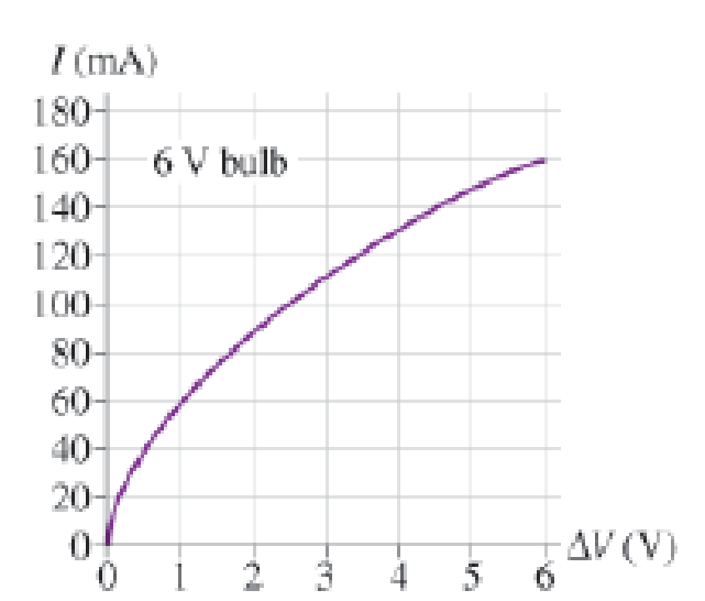
When the bulb is turned on, the filament is cold and its resistance is much lower than during normal, high-temperature operation. The low resistance causes a surge of higher-than-normal current lasting a fraction of a second until the filament heats up. Because power dissipation is I2R, the power dissipated during this first fraction of a second is much larger than the bulb’s rated power. This current surge concentrates the power dissipation at the high-resistance thin spot, perhaps melting it and breaking the filament.
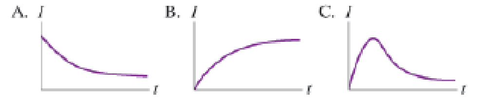
Which of the curves in Figure P22.72 best represents the expected variation in current as a function of time in the short time interval immediately after the bulb is turned on?
Figure P22.72
Want to see the full answer?
Check out a sample textbook solution
Chapter 22 Solutions
College Physics: A Strategic Approach (3rd Edition)
Additional Science Textbook Solutions
Human Physiology: An Integrated Approach (8th Edition)
Microbiology: An Introduction
Human Anatomy & Physiology (2nd Edition)
Campbell Essential Biology with Physiology (5th Edition)
Introductory Chemistry (6th Edition)
Microbiology: An Introduction


- A convex mirror (f.=-6.20cm) and a concave minor (f2=8.10 cm) distance of 15.5cm are facing each other and are separated by a An object is placed between the mirrors and is 7.8cm from each mirror. Consider the light from the object that reflects first from the convex mirror and then from the concave mirror. What is the distance of the image (dia) produced by the concave mirror? cm.arrow_forwardAn amusement park spherical mirror shows park spherical mirror shows anyone who stands 2.80m in front of it an upright image one and a half times the person's height. What is the focal length of the minor? m.arrow_forwardAn m = 69.0-kg person running at an initial speed of v = 4.50 m/s jumps onto an M = 138-kg cart initially at rest (figure below). The person slides on the cart's top surface and finally comes to rest relative to the cart. The coefficient of kinetic friction between the person and the cart is 0.440. Friction between the cart and ground can be ignored. (Let the positive direction be to the right.) m M (a) Find the final velocity of the person and cart relative to the ground. (Indicate the direction with the sign of your answer.) m/s (b) Find the friction force acting on the person while he is sliding across the top surface of the cart. (Indicate the direction with the sign of your answer.) N (c) How long does the friction force act on the person? S (d) Find the change in momentum of the person. (Indicate the direction with the sign of your answer.) N.S Find the change in momentum of the cart. (Indicate the direction with the sign of your answer.) N.S (e) Determine the displacement of the…arrow_forward
- Small ice cubes, each of mass 5.60 g, slide down a frictionless track in a steady stream, as shown in the figure below. Starting from rest, each cube moves down through a net vertical distance of h = 1.50 m and leaves the bottom end of the track at an angle of 40.0° above the horizontal. At the highest point of its subsequent trajectory, the cube strikes a vertical wall and rebounds with half the speed it had upon impact. If 10 cubes strike the wall per second, what average force is exerted upon the wall? N ---direction--- ▾ ---direction--- to the top to the bottom to the left to the right 1.50 m 40.0°arrow_forwardThe magnitude of the net force exerted in the x direction on a 3.00-kg particle varies in time as shown in the figure below. F(N) 4 3 A 2 t(s) 1 2 3 45 (a) Find the impulse of the force over the 5.00-s time interval. == N⚫s (b) Find the final velocity the particle attains if it is originally at rest. m/s (c) Find its final velocity if its original velocity is -3.50 î m/s. V₁ m/s (d) Find the average force exerted on the particle for the time interval between 0 and 5.00 s. = avg Narrow_forward••63 SSM www In the circuit of Fig. 27-65, 8 = 1.2 kV, C = 6.5 µF, R₁ S R₂ R3 800 C H R₁ = R₂ = R3 = 0.73 MQ. With C completely uncharged, switch S is suddenly closed (at t = 0). At t = 0, what are (a) current i̟ in resistor 1, (b) current 2 in resistor 2, and (c) current i3 in resistor 3? At t = ∞o (that is, after many time constants), what are (d) i₁, (e) i₂, and (f) iz? What is the potential difference V2 across resistor 2 at (g) t = 0 and (h) t = ∞o? (i) Sketch V2 versus t between these two extreme times. Figure 27-65 Problem 63.arrow_forward
- Thor flies by spinning his hammer really fast from a leather strap at the end of the handle, letting go, then grabbing it and having it pull him. If Thor wants to reach escape velocity (velocity needed to leave Earth’s atmosphere), he will need the linear velocity of the center of mass of the hammer to be 11,200 m/s. Thor's escape velocity is 33532.9 rad/s, the angular velocity is 8055.5 rad/s^2. While the hammer is spinning at its maximum speed what impossibly large tension does the leather strap, which the hammer is spinning by, exert when the hammer is at its lowest point? the hammer has a total mass of 20.0kg.arrow_forwardIf the room’s radius is 16.2 m, at what minimum linear speed does Quicksilver need to run to stay on the walls without sliding down? Assume the coefficient of friction between Quicksilver and the wall is 0.236.arrow_forwardIn the comics Thor flies by spinning his hammer really fast from a leather strap at the end of the handle, letting go, then grabbing it and having it pull him. If Thor wants to reach escape velocity (velocity needed to leave Earth’s atmosphere), he will need the linear velocity of the center of mass of the hammer to be 11,200 m/s. A) If the distance from the end of the strap to the center of the hammer is 0.334 m, what angular velocity does Thor need to spin his hammer at to reach escape velocity? b) If the hammer starts from rest what angular acceleration does Thor need to reach that angular velocity in 4.16 s? c) While the hammer is spinning at its maximum speed what impossibly large tension does the leather strap, which the hammer is spinning by, exert when the hammer is at its lowest point? The hammer has a total mass of 20.0kg.arrow_forward
- The car goes from driving straight to spinning at 10.6 rev/min in 0.257 s with a radius of 12.2 m. The angular accleration is 4.28 rad/s^2. During this flip Barbie stays firmly seated in the car’s seat. Barbie has a mass of 58.0 kg, what is her normal force at the top of the loop?arrow_forwardConsider a hoop of radius R and mass M rolling without slipping. Which form of kinetic energy is larger, translational or rotational?arrow_forwardA roller-coaster vehicle has a mass of 571 kg when fully loaded with passengers (see figure). A) If the vehicle has a speed of 22.5 m/s at point A, what is the force of the track on the vehicle at this point? B) What is the maximum speed the vehicle can have at point B, in order for gravity to hold it on the track?arrow_forward
 Physics for Scientists and Engineers, Technology ...PhysicsISBN:9781305116399Author:Raymond A. Serway, John W. JewettPublisher:Cengage Learning
 Principles of Physics: A Calculus-Based TextPhysicsISBN:9781133104261Author:Raymond A. Serway, John W. JewettPublisher:Cengage Learning
 Physics for Scientists and Engineers: Foundations...PhysicsISBN:9781133939146Author:Katz, Debora M.Publisher:Cengage Learning
 College PhysicsPhysicsISBN:9781938168000Author:Paul Peter Urone, Roger HinrichsPublisher:OpenStax College
 Physics for Scientists and EngineersPhysicsISBN:9781337553278Author:Raymond A. Serway, John W. JewettPublisher:Cengage Learning