Concept explainers
(a)
The possibility of the situation and any other possibility of the situation.
(a)
Answer to Problem 42P
Yes, the situation is possible and the only possibility is placing the third wire at a distance at which the force between wire 1 and 3 balances the force between wire 2 and 3.
Explanation of Solution
Given info: The
The orientation of the wires is shown in the figure below.
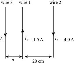
Figure (1)
The formula to calculate the magnitude of force per unit length is,
Here,
For the stability of wire 3 the magnetic force due to wire 1 on 3 must be equal to that of magnetic force due to wire 2 on 3
For equilibrium of wire 3,
From equation (1)
The above equation would be satisfied for only a particular position of wire 3 with respect to wire 1 and 2.
Thus, the situation is possible and the only possibility is placing the third wire at a distance at which the force between wire 1 and 3 balances the force between wire 2 and 3.
Conclusion:
Therefore, the situation is possible and the only possibility is placing the third wire at a distance at which the force between wire 1 and 3 balances the force between wire 2 and 3.
(b)
The position of wire 3.
(b)
Answer to Problem 42P
The position of wire 3 is
Explanation of Solution
Given info: The electric current in wire 1 is
The formula to calculate the magnitude of force per unit length is,
Here,
For the stability of wire 3 the magnetic force due to wire 1 on 3 must be equal to that of magnetic force due to wire 2 on 3
For equilibrium of wire 3,
From equation (2)
Substitute
The distance of the wire 3 is
Thus, the position of wire 3 is
Conclusion:
Therefore, the position of wire 3 is
(c)
The magnitude and direction of the current in wire 3.
(c)
Answer to Problem 42P
The magnitude of current in wire 3 is
Explanation of Solution
Given info: The electric current in wire 1 is
For the stability of wire 1 the magnetic force due to wire 1 on 3 must be equal to that of magnetic force due to wire 2 on 1
For equilibrium of wire 3,
From equation (2)
Here,
Substitute
The magnitude of electric current in wire 3 is
Conclusion:
Therefore, the magnitude of current in wire 3 is
Want to see more full solutions like this?
Chapter 22 Solutions
Principles of Physics: A Calculus-Based Text, Hybrid (with Enhanced WebAssign Printed Access Card)


- Four capacitors are connected as shown in the figure below. (Let C = 12.0 µF.) A circuit consists of four capacitors. It begins at point a before the wire splits in two directions. On the upper split, there is a capacitor C followed by a 3.00 µF capacitor. On the lower split, there is a 6.00 µF capacitor. The two splits reconnect and are followed by a 20.0 µF capacitor, which is then followed by point b. (a) Find the equivalent capacitance between points a and b. µF(b) Calculate the charge on each capacitor, taking ΔVab = 16.0 V. 20.0 µF capacitor µC 6.00 µF capacitor µC 3.00 µF capacitor µC capacitor C µCarrow_forwardTwo conductors having net charges of +14.0 µC and -14.0 µC have a potential difference of 14.0 V between them. (a) Determine the capacitance of the system. F (b) What is the potential difference between the two conductors if the charges on each are increased to +196.0 µC and -196.0 µC? Varrow_forwardPlease see the attached image and answer the set of questions with proof.arrow_forward
- How, Please type the whole transcript correctly using comma and periods as needed. I have uploaded the picture of a video on YouTube. Thanks,arrow_forwardA spectra is a graph that has amplitude on the Y-axis and frequency on the X-axis. A harmonic spectra simply draws a vertical line at each frequency that a harmonic would be produced. The height of the line indicates the amplitude at which that harmonic would be produced. If the Fo of a sound is 125 Hz, please sketch a spectra (amplitude on the Y axis, frequency on the X axis) of the harmonic series up to the 4th harmonic. Include actual values on Y and X axis.arrow_forwardSketch a sign wave depicting 3 seconds of wave activity for a 5 Hz tone.arrow_forward
- Sketch a sine wave depicting 3 seconds of wave activity for a 5 Hz tone.arrow_forwardThe drawing shows two long, straight wires that are suspended from the ceiling. The mass per unit length of each wire is 0.050 kg/m. Each of the four strings suspending the wires has a length of 1.2 m. When the wires carry identical currents in opposite directions, the angle between the strings holding the two wires is 20°. (a) Draw the free-body diagram showing the forces that act on the right wire with respect to the x axis. Account for each of the strings separately. (b) What is the current in each wire? 1.2 m 20° I -20° 1.2 marrow_forwardplease solve thisarrow_forward
- please solve everything in detailarrow_forward6). What is the magnitude of the potential difference across the 20-02 resistor? 10 Ω 11 V - -Imm 20 Ω 10 Ω 5.00 10 Ω a. 3.2 V b. 7.8 V C. 11 V d. 5.0 V e. 8.6 Varrow_forward2). How much energy is stored in the 50-μF capacitor when Va - V₁ = 22V? 25 µF b 25 µF 50 µFarrow_forward
 Physics for Scientists and Engineers, Technology ...PhysicsISBN:9781305116399Author:Raymond A. Serway, John W. JewettPublisher:Cengage Learning
 Physics for Scientists and Engineers: Foundations...PhysicsISBN:9781133939146Author:Katz, Debora M.Publisher:Cengage Learning
 Glencoe Physics: Principles and Problems, Student...PhysicsISBN:9780078807213Author:Paul W. ZitzewitzPublisher:Glencoe/McGraw-Hill
 Principles of Physics: A Calculus-Based TextPhysicsISBN:9781133104261Author:Raymond A. Serway, John W. JewettPublisher:Cengage Learning
 Physics for Scientists and EngineersPhysicsISBN:9781337553278Author:Raymond A. Serway, John W. JewettPublisher:Cengage Learning