Loose Leaf for Vector Mechanics for Engineers: Statics and Dynamics
12th Edition
ISBN: 9781259977206
Author: BEER, Ferdinand P., Johnston Jr., E. Russell, Mazurek, David, Cornwell, Phillip J., SELF, Brian
Publisher: McGraw-Hill Education
expand_more
expand_more
format_list_bulleted
Videos
Textbook Question
Chapter 2.2, Problem 2.39P
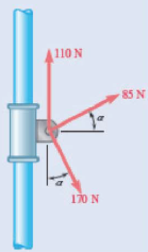
PROBLEM 2.39 A collar that can slide on a vertical rod is subjected to the three forces shown. Determine (a) the required value of α if the resultant of the three forces is to be horizontal, (b) the corresponding magnitude of the resultant.
Expert Solution & Answer
Want to see the full answer?
Check out a sample textbook solution
Students have asked these similar questions
A 22-lb block B rests as shown on a 28-lb bracket A. The coefficients of friction are μs=0.30μs=0.30 and μk=0.25μk=0.25 between block B and bracket A, and there is no friction in the pulley or between the bracket and the horizontal surface. solved in a previous part. max weight of block C if block B is not to slide on bracket A is 5.045 lbs. Please solve for the acceleration of each Block
Test 1 .DOCX * A
File Edit View
Tools Help
INDUSTRIAL ENGINEERING PROGRAMME
IMB 411-INDUSTRIAL LOGISTICS
TEST 1- SEPTEMBER 12, 2012
Instructions: Answer all questions. Time allowed is 1.5 hours. Identify your script with your
student number ONLY (Do not write your name).
1. Define the following terms
(i) Logistics management
(ii) Supply chain management
(iii) Vertical integration in a supply chain
(3 Marks)
(3 Marks)
(3 Marks)
2. (a) Using examples of your choice, briefly discuss the following levels of customer
service
(1) Pre-transaction elements
(ii) Transaction elements
(4 Marks)
(4 Marks)
(iii) Post-transaction elements
(4 Marks)
(b) "The challenge facing Dumelang Enterprise (Pty) Ltd is to establish the real
profitability of their customers and to develop service strategies that will improve the
profitability of all customers". As a logistics consultant, briefly discuss how you can
advise Dumelang's customer service management.
3. (a) List the three main forms of inventory in a…
It is decided to install several single-jet Pelton wheels to produce a total power of 18 MW. The
available head is 246 m. The wheel rotational speed is 650 rpm and the speed ratio (❤) = 0.46.
The diameter of the nozzle (jet) is limited to be 0.167 m with a Cv of 0.95. The efficiency of each
turbine is 87%. Determine: (1) The number of Pelton wheels to be used, and (2) The bucket
angle.
Chapter 2 Solutions
Loose Leaf for Vector Mechanics for Engineers: Statics and Dynamics
Ch. 2.1 - Two forces are applied as shown to a hook....Ch. 2.1 - Two forces are applied as shown to a bracket...Ch. 2.1 - Two forces P and Q are applied as shown at point A...Ch. 2.1 - Two forces P and Q are applied as shown at point A...Ch. 2.1 - A stake is being pulled out of the ground by means...Ch. 2.1 - A telephone cable is clamped at A to the pole AB....Ch. 2.1 - A telephone cable is clamped at A to the pole AB....Ch. 2.1 - A disabled automobile is pulled by means of two...Ch. 2.1 - A disabled automobile is pulled by means of two...Ch. 2.1 - Two forces are applied as shown to a hook support....
Ch. 2.1 - A steel tank is to be positioned in an excavation....Ch. 2.1 - A steel tank is to be positioned in an excavation....Ch. 2.1 - A steel tank is to be positioned in an excavation....Ch. 2.1 - For the hook support of Prob. 2.10, determine by...Ch. 2.1 - The barge B is pulled by two tugboats A and C. At...Ch. 2.1 - Solve Prob. 2.1 by trigonometry.Ch. 2.1 - Solve Prob. 2.4 by trigonometry.Ch. 2.1 - For the stake of Prob. 2.5, knowing that the...Ch. 2.1 - Two structural members A and B are bolted to a...Ch. 2.1 - Two structural members A and B are bolted to a...Ch. 2.2 - Determine the x and y components of each of the...Ch. 2.2 - Determine the x and y components of each of die...Ch. 2.2 - Determine the x and y components of each of the...Ch. 2.2 - Determine the x and y components of each of the...Ch. 2.2 - Member BC exerts on member AC a force P directed...Ch. 2.2 - Member BD exerts on member ABC a force P directed...Ch. 2.2 - Prob. 2.27PCh. 2.2 - Cable AC exerts on beam AD a force P directed...Ch. 2.2 - The hydraulic cylinder BD exerts on member ABC a...Ch. 2.2 - The guy wire BD exerts on the telephone pole AC a...Ch. 2.2 - Determine the resultant of the three forces of...Ch. 2.2 - Determine the resultant of the three forces of...Ch. 2.2 - Determine the resultant of the three forces of...Ch. 2.2 - Determine the resultant of the three forces of...Ch. 2.2 - Knowing that = 35, determine the resultant of the...Ch. 2.2 - Knowing that the tension in cable BC is 725 N,...Ch. 2.2 - Knowing that = 40, determine the resultant of the...Ch. 2.2 - Knowing that = 75, determine the resultant of the...Ch. 2.2 - PROBLEM 2.39 A collar that can slide on a vertical...Ch. 2.2 - PROBLEM 2.40 For the beam of Problem 2.36,...Ch. 2.2 - PROBLEM 2.41 Determine (a) the required tension in...Ch. 2.2 - PROBLEM 2.42 For the block of Problems 2.37 and...Ch. 2.3 - Two cables are tied together at C and loaded as...Ch. 2.3 - Two forces of magnitude TA = 8 kips and TB = 15...Ch. 2.3 - The 60-lb collar A can slide on a frictionless...Ch. 2.3 - A chairlift has been stopped in the position...Ch. 2.3 - Two cables are tied together at C and are loaded...Ch. 2.3 - Two cables are tied together at C and are loaded...Ch. 2.3 - Two cables are tied together at C and loaded as...Ch. 2.3 - Two cables are tied together at C and are loaded...Ch. 2.3 - Prob. 2.47PCh. 2.3 - Knowing that = 20, determine the tension (a) in...Ch. 2.3 - Two cables are tied together at C and are loaded...Ch. 2.3 - Two cables are tied together at C and are loaded...Ch. 2.3 - Prob. 2.51PCh. 2.3 - Two forces P and Q are applied as shown to an...Ch. 2.3 - A welded connection is in equilibrium under the...Ch. 2.3 - A welded connection is in equilibrium under the...Ch. 2.3 - A sailor is being rescued using a boatswains chair...Ch. 2.3 - A sailor is being rescued using a boatswains chair...Ch. 2.3 - For the cables of Prob. 2.44, find the value of ...Ch. 2.3 - For the cables of Prob. 2.46, it is known that the...Ch. 2.3 - For the situation described in Fig. P2.48,...Ch. 2.3 - Two cables tied together at C are loaded as shown....Ch. 2.3 - A movable bin and its contents have a combined...Ch. 2.3 - Prob. 2.62PCh. 2.3 - Collar A is connected as shown to a 50-lb load and...Ch. 2.3 - Collar A is connected as shown to a 50-lb load and...Ch. 2.3 - A cable loop of length 1.5 m is placed around a...Ch. 2.3 - A 200-kg crate is to be supported by the...Ch. 2.3 - A 600-lb crate is supported by several...Ch. 2.3 - Solve parts b and d of Prob. 2.67, assuming that...Ch. 2.3 - A load Q is applied to the pulley C, which can...Ch. 2.3 - An 1800-N load Q is applied to pulley C, which can...Ch. 2.4 - Determine (a) the x, y, and z components of the...Ch. 2.4 - Determine (a) the x, y, and z components of the...Ch. 2.4 - A gun is aimed at a point A located 35 east of...Ch. 2.4 - Solve Prob. 2.73 assuming that point A is located...Ch. 2.4 - The angle between the guy wire AB and the mast is...Ch. 2.4 - The angle between the guy wire AC and the mast is...Ch. 2.4 - Cable AB is 65 ft long, and the tension in that...Ch. 2.4 - PROBLEM 2.78 Cable AC is 70 ft long, and the...Ch. 2.4 - Determine the magnitude and direction of the force...Ch. 2.4 - Determine the magnitude and direction of the force...Ch. 2.4 - Prob. 2.81PCh. 2.4 - Prob. 2.82PCh. 2.4 - Prob. 2.83PCh. 2.4 - A force acts at the origin of a coordinate system...Ch. 2.4 - Two cables BG and BH are attached to frame ACD as...Ch. 2.4 - Two cables BG and BH are attached to frame ACD as...Ch. 2.4 - In order to move a wrecked truck, two cables are...Ch. 2.4 - In order to move a wrecked truck, two cables are...Ch. 2.4 - A rectangular plate is supported by three cables...Ch. 2.4 - A rectangular plate is supported by three cables...Ch. 2.4 - Find the magnitude and direction of the resultant...Ch. 2.4 - Prob. 2.92PCh. 2.4 - Knowing that the tension is 425 lb in cable AB and...Ch. 2.4 - Knowing that the tension is 510 lb in cable AB and...Ch. 2.4 - Prob. 2.95PCh. 2.4 - Prob. 2.96PCh. 2.4 - The boom OA carries a load P and is supported by...Ch. 2.4 - Fig. P2.97 2.98 For the boom and loading of Prob....Ch. 2.5 - Three cables are used to tether a balloon as...Ch. 2.5 - A container of mass m = 120 kg is supported by...Ch. 2.5 - A 150-lb cylinder is supported by two cables AC...Ch. 2.5 - A transmission tower is held by three guy wires...Ch. 2.5 - A container is supported by three cables that are...Ch. 2.5 - A container is supported by three cables that are...Ch. 2.5 - Three cables are used to tether a balloon as...Ch. 2.5 - Three cables are used to tether a balloon as...Ch. 2.5 - A crate is supported by three cables as shown....Ch. 2.5 - A crate is supported by three cables as shown....Ch. 2.5 - A 12-lb circular plate of 7-in. radius is...Ch. 2.5 - Solve Prob. 2.105, knowing that = 45.Ch. 2.5 - Three cables are connected at A, where the forces...Ch. 2.5 - Fig. P2.107 and P2.108 2.108 Three cables are...Ch. 2.5 - Prob. 2.109PCh. 2.5 - A rectangular plate is supported by three cables...Ch. 2.5 - A transmission tower is held by three guy wires...Ch. 2.5 - A transmission tower is held by three guy wires...Ch. 2.5 - In trying to move across a slippery icy surface, a...Ch. 2.5 - Fig. P2.113 2.114 Solve Prob. 2.113 assuming that...Ch. 2.5 - For the rectangular plate of Probs. 2.109 and...Ch. 2.5 - PROBLEM 2.116 For the cable system of Problems...Ch. 2.5 - PROBLEM 2.117 For the cable system of Problems...Ch. 2.5 - Three cables are connected at D, where an upward...Ch. 2.5 - For the transmission tower of Probs. 2.111 and...Ch. 2.5 - Three wires are connected at point D, which is...Ch. 2.5 - A container of weight W is suspended from ring A,...Ch. 2.5 - Prob. 2.122PCh. 2.5 - A container of weight W is suspended from ring A....Ch. 2.5 - Prob. 2.124PCh. 2.5 - Fig. P2.113 2.114 Solve Prob. 2.113 assuming that...Ch. 2.5 - Prob. 2.126PCh. 2 - Two forces P and Q are applied to the lid of a...Ch. 2 - Determine the x and y components of each of the...Ch. 2 - A hoist trolley is subjected to the three forces...Ch. 2 - Knowing that = 55 and that boom AC exerts on pin...Ch. 2 - Two cables are tied together at C and loaded as...Ch. 2 - Two cables tied together at C are loaded as shown....Ch. 2 - The end of the coaxial cable AE is attached to the...Ch. 2 - Prob. 2.134RPCh. 2 - Find the magnitude and direction of the resultant...Ch. 2 - Cable BAC passes through a frictionless ring A and...Ch. 2 - Collars A and B are connected by a 25-in.-lang...Ch. 2 - Fig. P2.137 and P2.138 2.138 Collars A and B are...
Knowledge Booster


Learn more about
Need a deep-dive on the concept behind this application? Look no further. Learn more about this topic, mechanical-engineering and related others by exploring similar questions and additional content below.Similar questions
- (I) [40 Points] Using centered finite difference approximations as done in class, solve the equation for O: d20 dx² + 0.010+ Q=0 subject to the boundary conditions shown in the stencil below. Do this for two values of Q: (a) Q = 0.3, and (b) Q= √(0.5 + 2x)e-sinx (cos(5x)+x-0.5√1.006-x| + e −43*|1+.001+x* | * sin (1.5 − x) + (cosx+0.001 + ex-1250+ sin (1-0.9x)|) * x - 4.68x4. For Case (a) (that is, Q = 0.3), use the stencil in Fig. 1. For Case (b), calculate with both the stencils in Fig. 1 and Fig 2. For all the three cases, show a table as well as a plot of O versus x. Discuss your results. Use MATLAB and hand in the MATLAB codes. 1 0=0 x=0 2 3 4 0=1 x=1 Fig 1 1 2 3 4 5 6 7 8 9 10 11 0=0 x=0 0=1 x=1 Fig 2arrow_forwardFig 2 (II) [60 Points] Using centered finite difference approximation as done in class, solve the equation: 020 020 + მx2 მy2 +0.0150+Q=0 subject to the boundary conditions shown in the stencils below. Do this for two values of Q: (a) Q = 0.3, and (b) Q = 10.5x² + 1.26 * 1.5 x 0.002 0.008. For Case (a) (that is, Q = 0.3) use Fig 3. For Case (b), use both Fig. 3 and Fig 4. For all the three cases, show a table as well as the contour plots of versus (x, y), and the (x, y) heat flux values at all the nodes on the boundaries x = 1 and y = 1. Discuss your results. Use MATLAB and hand in the MATLAB codes. (Note that the domain is (x, y)e[0,1] x [0,1].) 0=0 0=0 4 8 12 16 10 Ꮎ0 15 25 9 14 19 24 3 11 15 0=0 8-0 0=0 3 8 13 18 23 2 6 сл 5 0=0 10 14 6 12 17 22 1 6 11 16 21 13 e=0 Fig 3 Fig 4 Textbook: Numerical Methods for Engineers, Steven C. Chapra and Raymond P. Canale, McGraw-Hill, Eighth Edition (2021).arrow_forwardShip construction question. Sketch and describe the forward arrangements of a ship. Include componets of the structure and a explanation of each part/ term. Ive attached a general fore end arrangement. Simplfy construction and give a brief describion of the terms.arrow_forward
- Problem 1 Consider R has a functional relationship with variables in the form R = K xq xx using show that n ✓ - (OR 1.) = i=1 2 Их Ux2 Ихэ 2 (177)² = ² (1)² + b² (12)² + c² (1)² 2 UR R x2 x3arrow_forward4. Figure 3 shows a crank loaded by a force F = 1000 N and Mx = 40 Nm. a. Draw a free-body diagram of arm 2 showing the values of all forces, moments, and torques that act due to force F. Label the directions of the coordinate axes on this diagram. b. Draw a free-body diagram of arm 2 showing the values of all forces, moments, and torques that act due to moment Mr. Label the directions of the coordinate axes on this diagram. Draw a free body diagram of the wall plane showing all the forces, torques, and moments acting there. d. Locate a stress element on the top surface of the shaft at A and calculate all the stress components that act upon this element. e. Determine the principal stresses and maximum shear stresses at this point at A.arrow_forward3. Given a heat treated 6061 aluminum, solid, elliptical column with 200 mm length, 200 N concentric load, and a safety factor of 1.2, design a suitable column if its boundary conditions are fixed-free and the ratio of major to minor axis is 2.5:1. (Use AISC recommended values and round the ellipse dimensions so that both axes are whole millimeters in the correct 2.5:1 ratio.)arrow_forward
- 1. A simply supported shaft is shown in Figure 1 with w₁ = 25 N/cm and M = 20 N cm. Use singularity functions to determine the reactions at the supports. Assume El = 1000 kN cm². Wo M 0 10 20 30 40 50 60 70 80 90 100 110 cm Figure 1 - Problem 1arrow_forwardPlease AnswerSteam enters a nozzle at 400°C and 800 kPa with a velocity of 10 m/s and leaves at 375°C and 400 kPa while losing heat at a rate of 26.5 kW. For an inlet area of 800 cm2, determine the velocity and the volume flow rate of the steam at the nozzle exit. Use steam tables. The velocity of the steam at the nozzle exit is m/s. The volume flow rate of the steam at the nozzle exit is m3/s.arrow_forward2. A support hook was formed from a rectangular bar. Find the stresses at the inner and outer surfaces at sections just above and just below O-B. -210 mm 120 mm 160 mm 400 N B thickness 8 mm = Figure 2 - Problem 2arrow_forward
arrow_back_ios
SEE MORE QUESTIONS
arrow_forward_ios
Recommended textbooks for you
 Elements Of ElectromagneticsMechanical EngineeringISBN:9780190698614Author:Sadiku, Matthew N. O.Publisher:Oxford University Press
 Mechanics of Materials (10th Edition)Mechanical EngineeringISBN:9780134319650Author:Russell C. HibbelerPublisher:PEARSON
 Thermodynamics: An Engineering ApproachMechanical EngineeringISBN:9781259822674Author:Yunus A. Cengel Dr., Michael A. BolesPublisher:McGraw-Hill Education
 Control Systems EngineeringMechanical EngineeringISBN:9781118170519Author:Norman S. NisePublisher:WILEY
 Mechanics of Materials (MindTap Course List)Mechanical EngineeringISBN:9781337093347Author:Barry J. Goodno, James M. GerePublisher:Cengage Learning
 Engineering Mechanics: StaticsMechanical EngineeringISBN:9781118807330Author:James L. Meriam, L. G. Kraige, J. N. BoltonPublisher:WILEY
Elements Of Electromagnetics
Mechanical Engineering
ISBN:9780190698614
Author:Sadiku, Matthew N. O.
Publisher:Oxford University Press
Mechanics of Materials (10th Edition)
Mechanical Engineering
ISBN:9780134319650
Author:Russell C. Hibbeler
Publisher:PEARSON
Thermodynamics: An Engineering Approach
Mechanical Engineering
ISBN:9781259822674
Author:Yunus A. Cengel Dr., Michael A. Boles
Publisher:McGraw-Hill Education
Control Systems Engineering
Mechanical Engineering
ISBN:9781118170519
Author:Norman S. Nise
Publisher:WILEY
Mechanics of Materials (MindTap Course List)
Mechanical Engineering
ISBN:9781337093347
Author:Barry J. Goodno, James M. Gere
Publisher:Cengage Learning
Engineering Mechanics: Statics
Mechanical Engineering
ISBN:9781118807330
Author:James L. Meriam, L. G. Kraige, J. N. Bolton
Publisher:WILEY
How to balance a see saw using moments example problem; Author: Engineer4Free;https://www.youtube.com/watch?v=d7tX37j-iHU;License: Standard Youtube License